


L-DALI User Manual
28
LOYTEC
Version 5.2
LOYTEC electronics GmbH
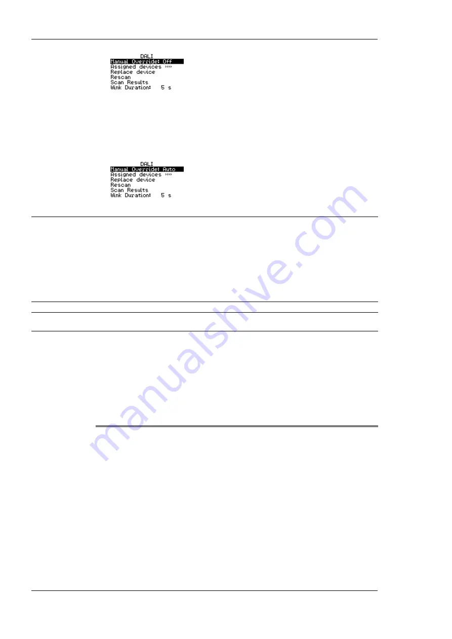
Now all DALI ballasts should be switched off and the status LED on the L-DALI
should light up orange.
7.
Turn the dial one step right once more. This should not change the state of the DALI
ballasts but return the manual override back to the auto-mode (control via
CEA-709/BACnet interface).
3.2 Device configuration
The L-DALI can be configured via a console interface or via the Web interface. To
configure the L-DALI, the following steps have to be performed:
1.
Setup IP configuration (see Sections 3.2).
2.
Setup the DALI network (see Section 3.4 or 3.5).
Note:
This setup procedure assumes the use of the IP interface.
3.3 Configuration of IP Address
3.3.1 IP Configuration via Console
If your model is equipped with a console interface use a standard null-modem cable with
full handshaking to connect COM1 of the PC to the Console on the device. Use a PC
terminal program with the communication settings set to 38,400 bps / 8 data bits / no parity
/ 1 stop bit / no handshake. Power up the device or press
Return
if the device is already
running. The following menu should appear on the terminal:
Device Main Menu
[1] Show device information
[2] Serial firmware upgrade
[3] System configuration
[4] DALI maintenance
[5] IP configuration
[6] CEA-852 device configuration
[7] CEA-709 configuration
[8] Reset configuration (factory defaults)
[9] Device statistics
[a] Data Points
[0] Reset device
Please choose:
Figure 7: Device Main Menu.
Select ‘5’ from the device main menu and enter the IP address, netmask, and gateway
address. Note that you must use different IP addresses if you are using multiple IP devices
in your setup.


