


8.SUSPENSION SYSTEM
8-
4
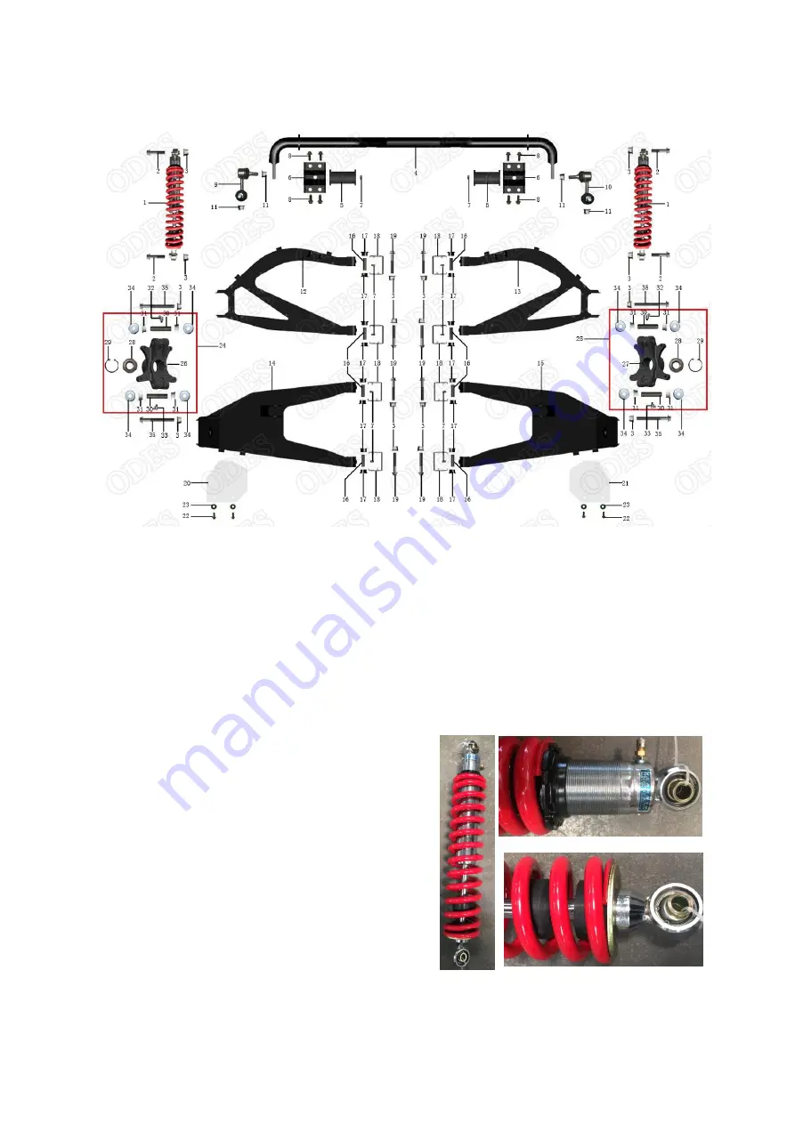
REAR SUSPENSION
The procedure explained below is the same for the RH and LH sides unless otherwise noted. During
assembly or installation, use the torque values and service products as in the torque table
REMOVAL AND DISASSEMBLY
Loosen wheel nut of the appropriate.
Install a jack stand under the frame to lift the rear of vehicle off the ground until the shock absorber is
fully extended.
Remove
wheels, brake caliper and hub
remove steering knuckle from ball cage tie rod
INSPECTION
Shock absorber
Inspect the shock absorber for oil leakage or damage,
inspect the bushing for wear or damage. If any damage
are found, replace the rear shock absorber with a new
one.
Extend and compress the piston several times over its
entire stroke. Check that it moves smoothly and with
uniform resistance with rod up. Any of the following
conditions will denote a defective shock:
●
A skip or hang up when reversing stroke at
mid-travel.
●
Seizing or binding conditions except at extreme end of either stroke.
●
A gurgling noise after completing one full compression and extension stroke.
Summary of Contents for UTV1000-3
Page 10: ......
Page 30: ......
Page 38: ...3 ENGINE 3 8 LUBRICATION SYSTEM COMPONENTS...
Page 47: ...3 ENGINE 3 17 MAGNETO SYSTEM...
Page 75: ...3 ENGINE 3 47 ENGINE DRIVE SHAFT CRANKCASE AND PTO COVER...
Page 76: ...3 ENGINE 3 48 CRANKSHAFT...
Page 77: ...3 ENGINE 3 49...
Page 101: ...3 ENGINE 3 73 GEARBOX...
Page 130: ......
Page 142: ......
Page 152: ...8 SUSPENSION SYSTEM 8 6...
Page 160: ......
Page 170: ......


