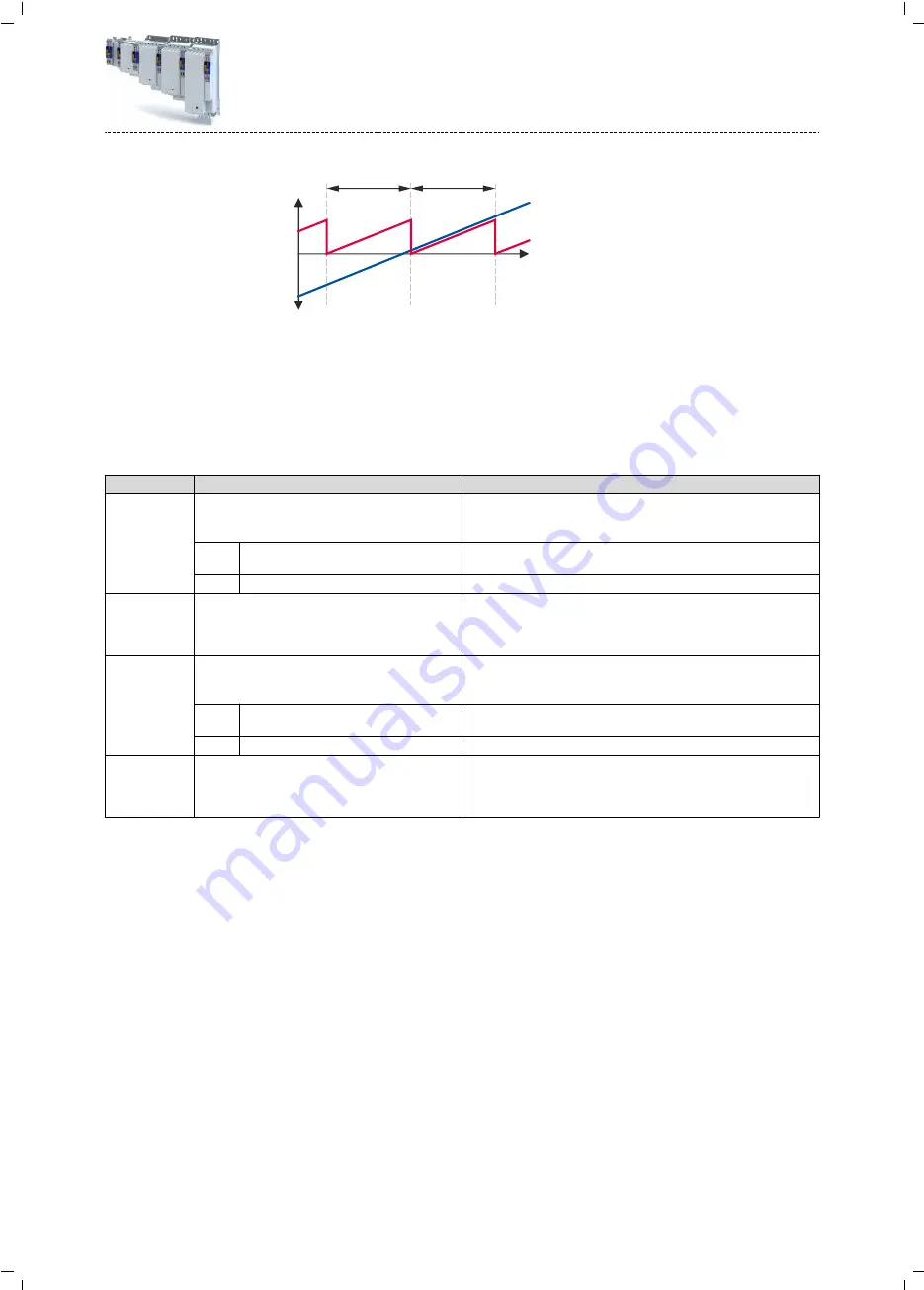
❶
❷
❸
❶
t
Fig. 6: Position representation
1
Cycle length
2
Position in the machine measuring
system
3
Position in the motor measuring sys-
tem
The kinematic parameters for the second encoder serve to define the conversion of an impor-
ted encoder position or encoder speed in machine units.
Parameter
Address
Name / setting range / [default setting]
Info
0x500A:030
Travel range
•
Setting can only be changed if the inverter is inhibi-
ted.
Selection of the traversing range for the motor
0 Modulo
Unlimited traversing range (turntable). The cycle length must also be
specified here.
1 Limited
Linearly limited traversing range (spindle drive).
0x500A:031
Cycle length
0.0001 ... [360.0000] ... 214748.3647
•
Setting can only be changed if the inverter is inhibi-
ted.
The cycle length for an unlimited traversing range defines the position
where the measuring system is repeated (position return to 0).
0x500B:030
Travel range
•
Setting can only be changed if the inverter is inhibi-
ted.
Selection of the traversing range with regard to the encoder position.
0 Modulo
Unlimited traversing range (turntable). The cycle length must also be
specified here.
1 Limited
Linearly limited traversing range (spindle drive).
0x500B:031
Cycle length
0.0001 ... [360.0000] ... 214748.3647
•
Setting can only be changed if the inverter is inhibi-
ted.
The cycle length for an unlimited traversing range defines the position
where the measuring system is repeated (position return to 0).
Technology application (TA) basic settings
Kinematic settings
Motor/encoder travel ranges and cycle length
51
Summary of Contents for i950 Series
Page 1: ...Inverters i950 servo inverters Commissioning EN ...
Page 2: ......
Page 497: ......
Page 498: ......
Page 499: ......


