


CHAPTER 12 POSITIONING DATA
12-10
Settings
12
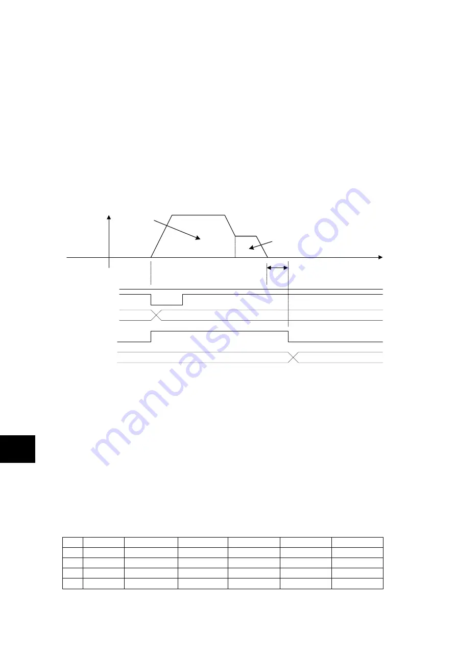
Data continuation (CO)
When the motor is started up by positioning data with data continuation specified, positioning is
completed by the data, and then the motor moves according to the setting of the next positioning
data.
If data continuation is specified on positioning data 5, the motor moves according to positioning data 6.
In the same way, if data continuation is specified on positioning data 6, the motor moves according
to positioning data 7.
If the stop timer is set to 0.00 [s], traveling speed varies continuously.
If the stop timer is set to 0.00 [s], speed varies depending on the setting of positioning data.
(1) When data with a high speed is continued to data with a low speed, speed has already been
reduced to the next speed data at the specified position of the positioning data.
(2) When data with a low speed is continued to data with a high speed, acceleration is started from
the specified position of the positioning data.
Data continuation is executed in the order of positioning data numbers (addresses).
When the motor is started up at positioning data while data continuation is executed, the positioning
data before the start up are ignored.
(Data continuation is not executed as tracing back positioning data.)
When the motor is started up from No.7 using the following positioning data, the setting of No.6 is
ignored.
Rotation
speed
Ready
Data continuation of positioning data
Time
ON
ON
OFF
Start
positioning
AD4-AD0
5
**
In position
(lNP)
ON
OFF
ON
M code (output after
position completion)
Stand still timer
(stop time)
・
Positioning data are regarded as being executed while timer is measured.
・
The default value of the M code is "FF" (changeable into "00" by PA2_43).
FF
20
No. 5
No. 6
6
Data continuation of positioning data
No.
Command style
Stop position
0.00
7
8
9
ABS
Step mode
CO
CO
CO
5000.00
5200.00
5400.00
ABS
ABS
ABS
Rotation speed
0.00
5000.00
500.00
50.00
**
**
Summary of Contents for ALPHA7
Page 1: ......
Page 3: ...ii...
Page 22: ...0 1 CHAPTER 0 INTRODUCTION 0...
Page 36: ...1 1 CHAPTER 1 INSTALLATION 1...
Page 47: ...CHAPTER 1 INSTALLATION 1 12 Servo Amplifier 1...
Page 48: ...2 1 CHAPTER 2 WIRING 2...
Page 163: ...CHAPTER 2 WIRING 2 116 Safety Function 2...
Page 164: ...3 1 CHAPTER 3 OPERATION 3...
Page 192: ...4 1 CHAPTER 4 PARAMETER 4...
Page 317: ...CHAPTER 4 PARAMETER 4 126 Extension Function 2 Setting Parameters 4...
Page 318: ...5 1 CHAPTER 5 SERVO ADJUSTMENT 5...
Page 353: ...CHAPTER 5 SERVO ADJUSTMENT 5 36 Special Adjustment Vibration Suppression 5...
Page 354: ...6 1 CHAPTER 6 KEYPAD 6...
Page 408: ...7 1 CHAPTER 7 MAINTENANCE AND INSPECTION 7...
Page 434: ...8 1 CHAPTER 8 SPECIFICATIONS 8...
Page 460: ...9 1 CHAPTER 9 CHARACTERISTICS 9...
Page 472: ...10 1 CHAPTER 10 PERIPHERAL EQUIPMENT 10...
Page 516: ...11 1 CHAPTER 11 ABSOLUTE POSITION SYSTEM 11...
Page 523: ...CHAPTER 11 ABSOLUTE POSITION SYSTEM 11 8 Calculation of Battery Life 11...
Page 524: ...12 1 CHAPTER 12 POSITIONING DATA 12...
Page 540: ...13 1 CHAPTER 13 MODBUS RTU COMMUNICATION 13...
Page 579: ...CHAPTER 13 MODBUS RTU COMMUNICATION 13 40 Communications Procedures 13...
Page 580: ...14 1 CHAPTER 14 PC LOADER 14...
Page 614: ...STANDARDS COMPLIANCE CHAPTER 15 15...
Page 628: ...CHAPTER 16 APPENDIXES 16...
Page 661: ...CHAPTER 16 APPENDIXES 34 Product Warranty 16 16 7 Product Warranty...
Page 662: ......


