


CHAPTER 4 PARAMETER
Control Gain and Filter Setting Parameters
4-33
4
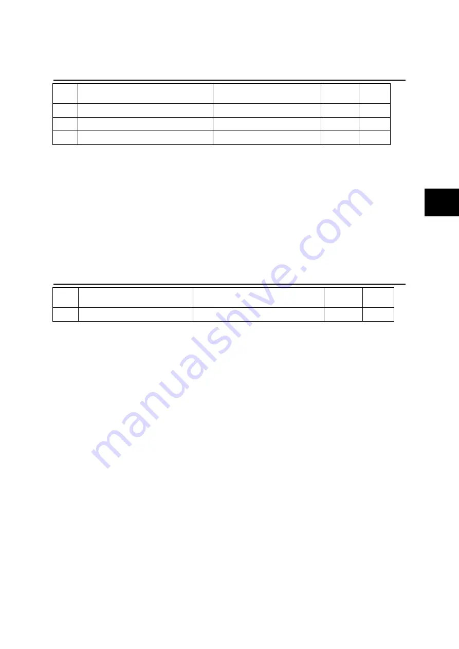
PA1_55 to 57 Response to disturbance settings
No.
Name
Setting range
Default
value
Change
55 Position loop gain 1
1 [rad/s] to 2000 [rad/s]
***
Always
56 Speed loop gain 1
1 [Hz] to 2000 [Hz]
***
Always
57 Speed loop integration time constant 1 0.5 [ms] to 1000.0 [ms]
***
Always
Position loop gain 1: Position disturbance response setting. A larger setting improves the response
characteristics.
Speed loop gain 1: Speed disturbance setting. A larger setting improves the response characteristics.
Speed loop integration time constant 1: Integration time constant setting of speed response. A smaller
setting improves the response.
Too much a response characteristic may cause vibration or noise.
When PA4_21 (torque control speed limit method) is set to "0" (PI control), the response characteristics
with operations by speed limit at torque control are determined by the setting values of PA1_56 and
PA1_57.
Automatic adjustment is made inside the amplifier if PA1_13 (tuning mode selection) is other than 2
(manual tuning).
PA1_58 Feed forward gain 1
No.
Name
Setting range
Default
value
Change
58
Feed forward gain 1
0.000 to 1.500
0.000
Always
A larger setting decreases the position deviation amount, improving the response characteristics.
Set at 1.000 to reduce the position deviation at a constant speed to almost zero (except during
acceleration or deceleration).
Use this parameter to increase the synchronization accuracy between two axes of synchronous control
or similar.
For regular point-to-point operation, set the parameter at 0.500 or less (approximate value).
Summary of Contents for ALPHA7
Page 1: ......
Page 3: ...ii...
Page 22: ...0 1 CHAPTER 0 INTRODUCTION 0...
Page 36: ...1 1 CHAPTER 1 INSTALLATION 1...
Page 47: ...CHAPTER 1 INSTALLATION 1 12 Servo Amplifier 1...
Page 48: ...2 1 CHAPTER 2 WIRING 2...
Page 163: ...CHAPTER 2 WIRING 2 116 Safety Function 2...
Page 164: ...3 1 CHAPTER 3 OPERATION 3...
Page 192: ...4 1 CHAPTER 4 PARAMETER 4...
Page 317: ...CHAPTER 4 PARAMETER 4 126 Extension Function 2 Setting Parameters 4...
Page 318: ...5 1 CHAPTER 5 SERVO ADJUSTMENT 5...
Page 353: ...CHAPTER 5 SERVO ADJUSTMENT 5 36 Special Adjustment Vibration Suppression 5...
Page 354: ...6 1 CHAPTER 6 KEYPAD 6...
Page 408: ...7 1 CHAPTER 7 MAINTENANCE AND INSPECTION 7...
Page 434: ...8 1 CHAPTER 8 SPECIFICATIONS 8...
Page 460: ...9 1 CHAPTER 9 CHARACTERISTICS 9...
Page 472: ...10 1 CHAPTER 10 PERIPHERAL EQUIPMENT 10...
Page 516: ...11 1 CHAPTER 11 ABSOLUTE POSITION SYSTEM 11...
Page 523: ...CHAPTER 11 ABSOLUTE POSITION SYSTEM 11 8 Calculation of Battery Life 11...
Page 524: ...12 1 CHAPTER 12 POSITIONING DATA 12...
Page 540: ...13 1 CHAPTER 13 MODBUS RTU COMMUNICATION 13...
Page 579: ...CHAPTER 13 MODBUS RTU COMMUNICATION 13 40 Communications Procedures 13...
Page 580: ...14 1 CHAPTER 14 PC LOADER 14...
Page 614: ...STANDARDS COMPLIANCE CHAPTER 15 15...
Page 628: ...CHAPTER 16 APPENDIXES 16...
Page 661: ...CHAPTER 16 APPENDIXES 34 Product Warranty 16 16 7 Product Warranty...
Page 662: ......


