


CHAPTER 6 KEYPAD
Test Operation Mode
6-49
6
4
SET
(1 sec. or over)
ESC
SET
(1 sec. or over)
ESC
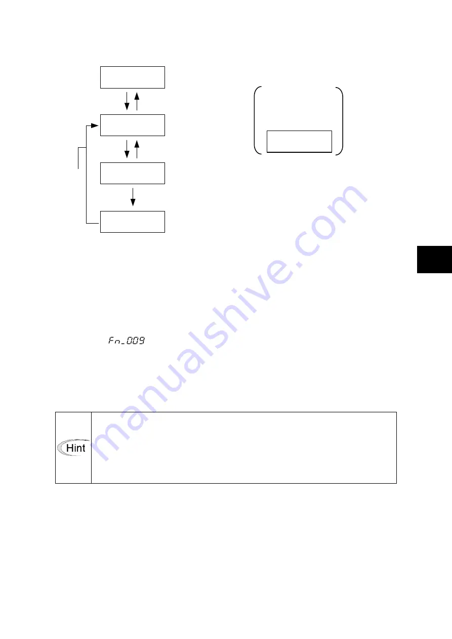
Test operation name
NG indication example
If NG displayed, refer to
“■ NG indication”
.
During execution
Initialization complete
ESC
Fn_09
Ad.oFF
_G_o_
donE
nG4
-
In speed control mode, when multi-step speed selection X1 and X2 terminals are all turned off by
the FWD (REV) signal, the output shaft of the servo motor rotates by following the analog speed
command voltage.
The output shaft of the servomotor may rotate at a small speed even if the speed command
voltage is 0 [V].
Use the "Zero clamp level (parameter PA3_35)" when necessary.
Follow the procedure below to adjust the offset voltage.
[1] Supply voltage 0 [V] to the [VREF] and [TREF] terminals. The operation command is not
necessary.
[2] Select [
] at the keypad and press the [SET/SHIFT] key to automatically adjust the
offset.
[3] Turn the operation command [S-ON] signal on and check that the output shaft of the
servomotor does not rotate.
*1) Cause of NG indication
Parameter PA2_75 (positioning data write protection) is set at 1 (write protected).
The adjusted result is stored in parameters PA3_32 and PA3_34.
According to variation in the ambient environment of the servo amplifier, offset
adjustment may become necessary. However, do not select if the host controller uses
the command voltage and division output pulse (feedback) to control the servo
amplifier.
(10) Z-phase position offset
The current position is defined to be the Z-phase position. After the Z-phase offset is defined, the
distance between the current position and Z-phase is automatically entered in parameter PA1_12
(Z-phase offset).
Summary of Contents for ALPHA7
Page 1: ......
Page 3: ...ii...
Page 22: ...0 1 CHAPTER 0 INTRODUCTION 0...
Page 36: ...1 1 CHAPTER 1 INSTALLATION 1...
Page 47: ...CHAPTER 1 INSTALLATION 1 12 Servo Amplifier 1...
Page 48: ...2 1 CHAPTER 2 WIRING 2...
Page 163: ...CHAPTER 2 WIRING 2 116 Safety Function 2...
Page 164: ...3 1 CHAPTER 3 OPERATION 3...
Page 192: ...4 1 CHAPTER 4 PARAMETER 4...
Page 317: ...CHAPTER 4 PARAMETER 4 126 Extension Function 2 Setting Parameters 4...
Page 318: ...5 1 CHAPTER 5 SERVO ADJUSTMENT 5...
Page 353: ...CHAPTER 5 SERVO ADJUSTMENT 5 36 Special Adjustment Vibration Suppression 5...
Page 354: ...6 1 CHAPTER 6 KEYPAD 6...
Page 408: ...7 1 CHAPTER 7 MAINTENANCE AND INSPECTION 7...
Page 434: ...8 1 CHAPTER 8 SPECIFICATIONS 8...
Page 460: ...9 1 CHAPTER 9 CHARACTERISTICS 9...
Page 472: ...10 1 CHAPTER 10 PERIPHERAL EQUIPMENT 10...
Page 516: ...11 1 CHAPTER 11 ABSOLUTE POSITION SYSTEM 11...
Page 523: ...CHAPTER 11 ABSOLUTE POSITION SYSTEM 11 8 Calculation of Battery Life 11...
Page 524: ...12 1 CHAPTER 12 POSITIONING DATA 12...
Page 540: ...13 1 CHAPTER 13 MODBUS RTU COMMUNICATION 13...
Page 579: ...CHAPTER 13 MODBUS RTU COMMUNICATION 13 40 Communications Procedures 13...
Page 580: ...14 1 CHAPTER 14 PC LOADER 14...
Page 614: ...STANDARDS COMPLIANCE CHAPTER 15 15...
Page 628: ...CHAPTER 16 APPENDIXES 16...
Page 661: ...CHAPTER 16 APPENDIXES 34 Product Warranty 16 16 7 Product Warranty...
Page 662: ......


