FATEK SD3 Series Instruction Manual Download Page 98

 6

22

ALM−

23

49

OUT̲A

36

CMD̲PLS

26


28

CMD̲DIR

30

32

34

OUT̲B

38

OUT̲Z

40

SG

42

/485

44

46

48

50

/CMD̲PLS

27

29

31

/CMD̲DIR

33

35

37

/OUT̲A

39

/OUT̲B

41

/OUT̲Z

43

485

45

SG

47

1

24V

3

COM+

5

RESET

7

PCLR

9

CCWL

11

TLSEL1

13

MBRK

15

POSIN

17

MEND

/T-LIMIT

19

SRDY+

21

ALM+

25

2

G24V

4

SVON

6

HOLD

8

HOME

10

CWL

12

COM−

14

SERVO

16

HEND

18

OCZ

20

SRDY−

24

4. Connection

SD3 Series Instruction Manual

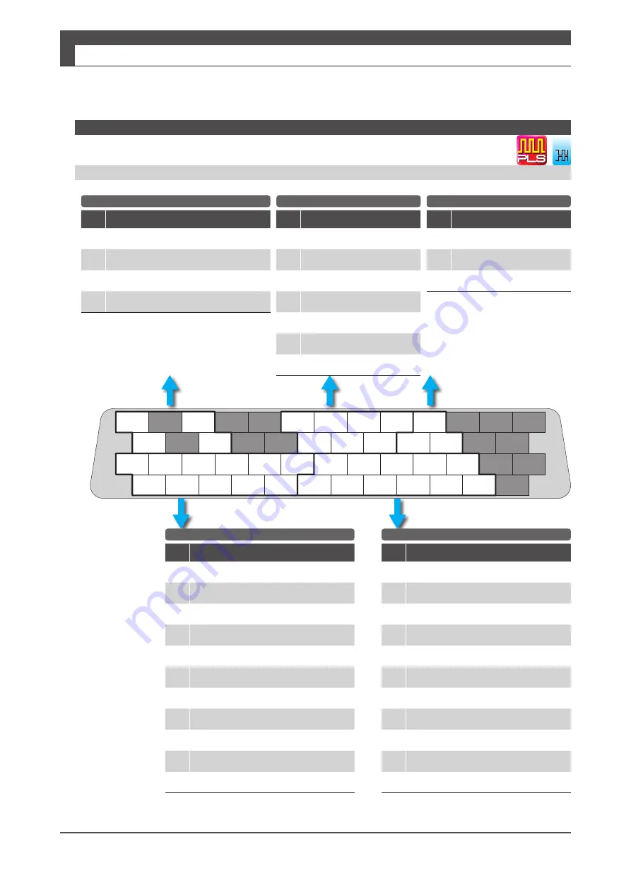
2. Position Control Mode

Pin

No.

Signal

Description

26

CMD_PLS

Pulse, QEP A-phase or CCW

27

/CMD_PLS

/Pulse, QEP /A-phase or /CCW

30

CMD_DIR

Direction, QEP B-phase or CW

31

/CMD_DIR

/Direction, QEP /B-phase or /CW

Pin

No.

Signal

Description

12

COM-

I/O power GND

13

MBRK

Brake release

14

SERVO

Servo status

15

POSIN

Positioning complete

16

HEND


(*)

Homing complete

17

MEND/T-LIMIT


(*)

Motion complete/Torque limiting 

18

OCZ

Encoder Z-phase (open collector)

19

SRDY+

Servo ready +

20

SRDY-

Servo ready-Servo ready -

21

ALM +

Alarm

22

ALM-

Alarm status -

Pin

No.

Signal

Description

1

24V

Control power 24 V

2

G24V

Control power GND

3

COM+

I/O Power 24 V

4

SVON

Servo ON

5

RESET

Alarm reset

6

HOLD

Command input prohibited

7

PCLR

Deviation counter clear

8

HOME


(*)

Homing start

9

CCWL

CCW drive restriction

10

CWL

CW drive restriction

11

TLSEL1

Torque Limit

Pin

No.

Signal

Description

36

OUT_A

A-phase

37

/OUT_A

/A-phase

38

OUT_B

B-phase

39

/OUT_B

/B-phase

40

OUT_Z

Z-phase

41

/OUT_Z

/Z-phase

42

SG

Signal ground

Pin

No.

Signal

Description

43

485

Data

44

/485

/Data

45

SG

Signal ground

Differential, I/O Setting Option 1

General-Purpose Input

General-Purpose Output

Command Input

Encoder Output

RS-485 Communication

QEP: Quadrature encoder pulse

I/O Connector pinout 

on the soldering surface

Pinout Diagram

*) For these pins function, change I/O setting with "Servo Studio".

dif.

Summary of Contents for SD3 Series

Page 1: ...R FATEK AUTOMATION CORP Instruction Manual AC SERVO MOTOR and SERVO AMPLIFIER SD3 Series...

Page 2: ...e product use Please study this manual first and use the product properly and safely Before using the product be sure to carefully read the Safety Instructions After reading this manual please keep it...

Page 3: ...3 Preparation Installation System Wiring and Timing Diagrams 4 Connections CN1 User I O Connector Pinout Options and Control Modes 5 Setting Parameters Setup Panel and Parameters 6 Operations Operatio...

Page 4: ...verview 11 1 Motor 2 2 Encoder 20 3 Amplifier 21 1 Installation 2 2 System Wiring 7 3 Timing Diagrams 28 1 Introduction 2 2 Position Control Mode 4 3 Velocity Control Mode 18 4 Torque Control Mode 22...

Page 5: ...d Alarms 2 2 Warnings and Remedies 5 3 Alarms and Remedies 8 4 Troubleshooting 17 1 Absolute System 2 2 Function 15 3 Technical Data 16 4 Status Display 17 5 How to set Pulse train command Input filte...

Page 6: ...6 MEMO SD3 Series Instruction Manual...

Page 7: ...1 Important Safety Instructions 2 1 Safety Precautions 2 2 Other Considerations and Precautions 7 3 Safety Standards 8 4 Maintenance and Inspection 9 5 Warranty 10 2 Overview 11 1 Product Label 12 2...

Page 8: ...ll result in death or serious injury CAUTION Identifies information about hazards that could result in injury or equipment damage Throughout this document the safety precautions that users must follow...

Page 9: ...r before wiring Wiring must be performed correctly Be sure with secure cable connections The current carrying components must be insulated Never touch the inside of the amplifier Be careful not to dam...

Page 10: ...tion work securely and properly Install external emergency stop circuitry so that the operation can be stopped and the power supply can be shut down immediately in case of emergency Never attempt to d...

Page 11: ...t in unstable motions Do not come close to the machinery right after power restoration following a power outage The machinery may restart unexpectedly at any moment Take appropriate measures to ensure...

Page 12: ...on manual Additional Precautions Maintenance and Inspection Prior to disposal of the batteries insulate them with tape or other material Dispose of them following the local laws and regulations When d...

Page 13: ...products Medical applications are not allowed Please contact us in advance of use Be sure to have safety device or protection device installed before using your equipment Doing so could become a fire...

Page 14: ...st conditions for the machinery and equipment with this product installed may be different from our test conditions Such machinery or equipment must meet the safety standards for their final configura...

Page 15: ...nance For safe use of the product perform daily and periodic inspections Daily Inspection Check the following before each operation Ambient temperature humidity and atmosphere No foreign objects or du...

Page 16: ...during the warranty period our company will make only fee based repair if the failure is due to the following reasons Misuse improper repair or alteration of the product Product is dropped after purch...

Page 17: ...he User Guide of your SD3 Series application product This is a high voltage product which can be hazardous Residual voltage exists at the terminals and inside the equipment even after power shutoff wh...

Page 18: ...No Serial No The product label is separated in two parts which are located shown in this picture Label 1 Label 2 Specifications Specifications Motor Label 1 kW to 2 kW Motor Model Specifications Prod...

Page 19: ...Amplifier Model Specifications The product label is located in the side cover of the amplifier About indication of the year I 2018 J 2019 About indication of the month 1 Jan 9 Sep X Oct Y Nov and Z D...

Page 20: ...burned from the heat Do not touch the amplifier during operation and within 5 minutes after operation or you may get injured Incorrect use of the amplifier may cause injury or damage Avoid misuse or...

Page 21: ...2 1 Models 2 2 Names of parts 3 3 Specifications 4 50 W 5 100 W 7 200 W 9 400 W 11 750 W 13 1 5 kW 17 2 kW 19 2 Encoder 20 1 Specifications 20 3 Amplifier 21 1 Models 21 2 Names of parts 22 3 Specifi...

Page 22: ...7 High Inertia Rated Output Code Rated Output 005 50 W 010 100 W 020 200 W 040 400 W 075 750 W 100 1 kW 150 1 5 kW 200 2 kW Brake Code Holding Brake N Without B With Oil Seal Code Oil Seal N Without...

Page 23: ...onnector Motor Power Connector Brake Connector Flange Mounting hole Thrust direction Shaft Radial direction Frame Encoder Cover Oilseal Oilseal Encoder Connector Motor Power Connector Brake Connector...

Page 24: ...rom corrosive gases flammable gases oil mist dust flammables grinding fluid Insulation resistance 5 M at 1 000 VDC Dielectric strength AC 1500 V for one minute across the primary and FG Operating alti...

Page 25: ...n 8 8 Rated power rate Without brake kW s 6 5 With brake 5 4 Mechanical time constant Without brake ms 1 92 With brake 2 31 Electrical time constant ms 0 74 Rotor moment of inertia Without brake 10 4...

Page 26: ...d voltage constant per phase mV r min 8 8 Rated power rate Without brake kW s 6 6 With brake 5 4 Mechanical time constant Without brake ms 2 02 With brake 2 45 Electrical time constant ms 0 65 Rotor m...

Page 27: ...2 Voltage V AC200 V to 240 V Rated output W 100 Rated torque N m 0 32 Instantaneous maximum torque N m 1 12 Rated current stall current A 0 97 Instantaneous maximum current A 3 3 Rated revolving speed...

Page 28: ...voltage constant per phase mV r min 12 3 Rated power rate Without brake kW s 15 8 With brake 14 1 Mechanical time constant Without brake ms 1 32 With brake 1 49 Electrical time constant ms 0 78 Rotor...

Page 29: ...stant per phase mV r min 14 3 Rated power rate Without brake kW s 28 2 With brake 23 5 Mechanical time constant Without brake ms 0 72 With brake 0 87 Electrical time constant ms 2 53 Rotor moment of i...

Page 30: ...se mV r min 14 3 Rated power rate Without brake kW s 9 1 With brake 8 6 Mechanical time constant Without brake ms 2 23 With brake 2 38 Electrical time constant ms 2 53 Rotor moment of inertia Without...

Page 31: ...tant per phase mV r min 17 1 Rated power rate Without brake kW s 69 4 With brake 61 8 Mechanical time constant Without brake ms 0 47 With brake 0 53 Electrical time constant ms 2 92 Rotor moment of in...

Page 32: ...Induced voltage constant per phase mV r min 17 1 Rated power rate Without brake kW s 23 0 With brake 22 1 Mechanical time constant Without brake ms 1 42 With brake 1 47 Electrical time constant ms 2 9...

Page 33: ...t per phase mV r min 21 9 Rated power rate Without brake kW s 76 6 With brake 60 7 Mechanical time constant Without brake ms 0 40 With brake 0 50 Electrical time constant ms 4 60 Rotor moment of inert...

Page 34: ...C312 Voltage V AC200 V to 240 V Rated output W 750 Rated torque N m 2 39 Instantaneous maximum torque N m 7 1 Rated current stall current A 4 2 Instantaneous maximum current A 12 2 Rated revolving spe...

Page 35: ...e mV r min 30 9 Rated power rate Without brake kW s 50 0 With brake 36 5 Mechanical time constant Without brake ms 0 76 With brake 1 05 Electrical time constant ms 10 1 Rotor moment of inertia Without...

Page 36: ...0 9 Rated power rate Without brake kW s 9 2 With brake 8 6 Mechanical time constant Without brake ms 4 17 With brake 4 43 Electrical time constant ms 10 1 Rotor moment of inertia Without brake 10 4 kg...

Page 37: ...er phase mV r min 28 4 Rated power rate Without brake kW s 76 9 With brake 61 4 Mechanical time constant Without brake ms 0 60 With brake 0 75 Electrical time constant ms 12 2 Rotor moment of inertia...

Page 38: ...Rated power rate Without brake kW s 13 8 With brake 13 3 Mechanical time constant Without brake ms 3 32 With brake 3 46 Electrical time constant ms 12 2 Rotor moment of inertia Without brake 10 4 kg...

Page 39: ...phase mV r min 29 6 Rated power rate Without brake kW s 104 9 With brake 87 9 Mechanical time constant Without brake ms 0 58 With brake 0 69 Electrical time constant ms 12 2 Rotor moment of inertia Wi...

Page 40: ...counts Maximum revolving speed 6 000 r min Count up direction CCW 2 Input output type Differential transform Communication specification Transmission method Half duplex asynchronous serial communicat...

Page 41: ...kW Three phase Use a motor and the amplifier in a correct combination Amplifier Motor Combinations Amplifier Motor Motor Rated Output Power SD3 005 CY12 M5B 005 C M5G 005 C 50 W SD3 010 CZ12 M5B 010 C...

Page 42: ...screw with spring washer Mounting holes 5 5 one location The recommended screw M5x12 mm with spring washer Setting panel Used for parameter setting tuning and status display CN3 PC communication conn...

Page 43: ...ector Encoder connection Mounting notch 5 5 one location The recommended screw M5x12 mm with spring washer Hazardous voltage display LED This will be lit while there is residual hazardous voltage insi...

Page 44: ...turn absolute type when batteries are added Control signal Input 8 point 24 VDC system photo coupler input insulation inputs whose functions are switched by the control mode Output 8 point 24 VDC sys...

Page 45: ...ration and storage Indoors not subject to direct sunlight Free from corrosive gases flammable gases oil mist dust flammables grinding fluid Altitude 1 000 m Vibration 5 8 m s2 0 6 G 10 to 60 Hz no con...

Page 46: ...ange B 1 to 65 535 Internal Position Control input Servo ON alarm reset deviation counter clear motion start point selection 16 home position sensor input homing start Control output Alarm status serv...

Page 47: ...eed is reached at 10 V Smoothing filter IIR Filter Torque Control Mode Common Features Item Specifications Speed observer Available Auto tuning Available Encoder output Division Multiplication Availab...

Page 48: ...e connected Current consumption by all I O signals in use must be added up If multiple amplifiers are to share control power select power source that will support the total inrush current of all conne...

Page 49: ...00 350 1 10 100 1000 2 Specifications Specifications SD3 Series Instruction Manual 3 Amplifier 3 Amplifier Torque Detection Time s Torque Detection Time s Torque Detection Time s Torque Detection Time...

Page 50: ...5 5 5 5 5 48 30 13 2 M5 160 150 5 mm 5 5 5 35 5 5 5 5 5 5 40 30 2 M5 160 150 5 5 130 12 5 12 160 40 16 10 6 5 mm 2 Specifications SD3 Series Instruction Manual 3 Amplifier Figure 1 Figure 2 4 Dimensi...

Page 51: ...19 160 30 10 6 68 mm 160 84 30 10 6 130 5 12 5 12 5 5 5 74 61 7 5 5 5 5 5 5 160 5 5 84 150 61 7 7 3 10 5 3 M5 1 5 mm 2 Specifications Specifications SD3 Series Instruction Manual 3 Amplifier 3 Amplif...

Page 52: ...32 MEMO 2 Specifications SD3 Series Instruction Manual...

Page 53: ...ifier Installation 5 2 System Wiring 7 1 System Wiring 8 2 Connecting Equipments and Recommended Peripherals 11 3 Wiring to the Connectors 14 Motor Connector Pinout 14 Amplifier Connectors and Pinouts...

Page 54: ...ee from dust iron dust and chips Do not use the product near locations exposed to high temperatures continuous vibrations or excessive shock The control power and the host control device must share on...

Page 55: ...alling the motor wipe off the oil completely Perform precise axis alignments Otherwise the motor operation will cause vibration or result in shorter service life of the motor Shock and Impact Force Wh...

Page 56: ...o a motor will be located over the motor shaft use an oil sealed motor so that no oil from the speed reducer permeates into the motor Types of Mounting and OilSeal SD3 series motors can be mounted in...

Page 57: ...to an enclosure such as protective casing use a fan or air conditioner so that the ambient temperature inside each board will not exceed 55 C The temperature of the heat sink at its surface may become...

Page 58: ...aluminum brushed plate Hook the U shaped installation notch of the amplifier to the bolt that has been screwed in advance Tighten the mounting screws on the amplifier top Loosely screw all amplifier...

Page 59: ...pply that the primary circuit power is connected to Do not use the electromagnetic contactor installed on the primary circuit power side to run or stop the motor Do not install a switch between the co...

Page 60: ...ltage Non dangerous voltage cable Explanatory notes Brake control circuit To connect to the Dedicated power supply unit Power supply for holding brake DC24 V Motor power cable Installation Using Pollu...

Page 61: ...circuit power High Voltage Non dangerous voltage cable Explanatory notes Brake control circuit To connect to the Dedicated power supply unit Power supply for holding brake DC24 V Motor power cable In...

Page 62: ...nit Power supply for holding brake DC24 V Motor power cable Installation Using Pollution degree 2 IEC 60664 1 Overvoltage Category IEC 60664 Ground resistance 100 max Control power DC24 V Servo Studio...

Page 63: ...for motor rated output are recommended Should you use a cable longer than the specification please contact us in advance Circuit breaker To protect the power supply line circuit breakers shut the cir...

Page 64: ...rcuit power supply An equivalent product is acceptable Select the capacity and other characteristics according to your entire system configuration Included in SD3 series amplifier s EMC testing Signal...

Page 65: ...is not equipped with a dynamic brake feature Use the following circuit example when building a dynamic brake circuit Select a cement resistor of 6 8 10 W Select coil surge protection relays with diod...

Page 66: ...nal ground 9 No Connect 1 Only for a motor equipped with a brake 2 Connect the negative pole of the battery to SG Signal Ground Motor 3 Wiring to the Connectors Motor Connector Pinout Encoder Connecto...

Page 67: ...ground 3 No Connect 4 BAT External battery 2 5 D Serial communication data Data 6 D Serial communication data Data 7 8 No Connect 9 SG Signal ground 10 SHIELD Shield Motor Pin orientations are viewed...

Page 68: ...ng PC Communication CN3 1 VBUS USB power supply 5 V 2 D USB data 3 D USB data 4 No Connect 5 SG USB signal ground User I O CN1 Route power and signal wiring suitable for your operation mode 4 Connecti...

Page 69: ...ELD wired to the connector casing PC Communication CN3 1 VBUS USB power supply 5 V 2 D USB data 3 D USB data 4 No Connect 5 SG USB signal ground User I O CN1 Route power and signal wiring suitable for...

Page 70: ...2 D USB data 3 D USB data 4 No Connect 5 SG USB signal ground User I O CN1 Route power and signal wiring suitable for your operation mode 4 Connections Amplifier 1 When having single phase power wire...

Page 71: ...orange part Gripping plate with a sliding connector release Orange colored part Connector release Locking latch Stripping cables with recommended tools Specialized Ferrule recommended For stranded wi...

Page 72: ...in until you hear a clicking sound Motor power connector Hold the frame of the connector and keep pushing in until you hear a clicking sound Primary circuit power connector The connector is fixed with...

Page 73: ...he tool insert the wire until it hits the round insertion slot the image to the left Release the pushbutton to finish the image in the middle Pull the wire slightly to verify that the wire connection...

Page 74: ...kW motors Encoder Power 22 Signal 24 20276 80 C 30 V Shielded twisted pair cables of length no exceeding 20 m User I O 26 1007 80 C 300 V Shielded twisted pair cables of length no exceeding 2 m Regene...

Page 75: ...JAPAN 6 SUMITUBE F Z 11x0 25 Sumitomo Electric Industries 7 MARKER TUBE arbitrary arbitrary Pin No Signal Color 1 U RED 2 V WHITE 3 W BLUE 4 FG GREEN YELLOW No Item Model Supplier 1 CABLE NA6CT 14 4 f...

Page 76: ...F Z 3 64 or 1 5x0 2 Sumitomo Electric Industries Pin No Signal 1 2 D 3 D 4 VCC 5 GND 6 SHIELD Pin No Signal 1 VCC 2 GND 3 4 5 D 6 D 7 SHIELD Shield No Item Model Supplier 1 CABLE NA20276TSB C for fixe...

Page 77: ...Tyco Electronics JAPAN 5 TERMINAL 170365 1 Tyco Electronics JAPAN 6 TERMINAL 170366 1 Tyco Electronics JAPAN 7 SUMITUBE F Z 7x0 25 Sumitomo Electric Industries 8 SUMITUBE F Z 3 64 or 1 5x0 2 Sumitomo...

Page 78: ...DK 5 TERMINAL CM10 22SC C1 D8 DDK 6 TERMINAL CM10 22SC C2 D8 DDK 7 SUMITUBE F Z 7x0 25 Sumitomo Electric Industries 8 SUMITUBE F Z 3 64 or 1 5x0 2 Sumitomo Electric Industries 9 HOUSING DF3 2EP 2C Hir...

Page 79: ...PAN 3 TERMINAL 170366 1 or 170639 1 Tyco Electronics JAPAN 4 SUMITUBE F Z 8x0 25 Sumitomo Electric Industries Pin No Signal Color 1 BRK BRACK 2 BRK BRACK No Item Model Supplier 1 CABLE MAST UL2517 19...

Page 80: ...ervo ON Page 34 7 Alarm Reset Servo OFF Page 35 8 Brake Release Page 36 9 Dynamic Brake Release Page 37 10 Deceleration Stop Status During Free Run Page 38 11 Delay time for Quick Stop Complete Page 3...

Page 81: ...1 After Clear Parameter execution T1 needs approximately 5 seconds for parameter initialization 2 SRDY turns ON when Primary Circuit Power and PRDY turns ON consecutively while Internal Error Status...

Page 82: ...tion Status remains OFF until Motor Rotational Speed drops to 30 r min or below 2 T1 is specified by Bake Release Delay Time No 238 0 Signal Description Name Timing Diagrams Output Transistor Status I...

Page 83: ...g Diagrams 3 Timing Diagrams 3 Servo ON OFF Motor idling T1 is specified by Servo OFF Delay time No 237 0 Signal Description Name Timing Diagrams Output Transistor Status I O Input Status and Internal...

Page 84: ...Method No 224 0 2 quick stop or 1 short brake MBRK turns OFF when one of the following conditions is met a Deceleration Stop Status turns OFF b The rotational speed drops to the value specified by De...

Page 85: ...us turns OFF If any of the following alarms occurs MBRK turns OFF when the internal error status becomes ERROR a Encoder related errors b Control Power voltage drop error c Errors related to Inverter...

Page 86: ...m Reset Servo ON 1 Motor Excitation Status remains OFF until motor rotational speed drops to 30 r min or below 2 T1 is specified by Bake release Delay time No 238 0 Signal Description Name Timing Diag...

Page 87: ...struction Manual Preparation 3 Timing Diagrams 3 Timing Diagrams 7 Alarm Reset Servo OFF Signal Description Name Timing Diagrams Output Transistor Status I O Input Status and Internal Status Main Circ...

Page 88: ...232 3 1 8 Brake Release 1 MBRK turns OFF is when one of the following becomes true a Deceleration Stop completes or b Motor rotational speed after the time specified by Parameter No 234 0 elapses drop...

Page 89: ...put No 224 3 1 dynamic brake after a stop per Deceleration Stop when Servo is OFF 9 Dynamic Brake Release Signal Description Name Timing Diagrams Output Transistor Status I O Input Status and Internal...

Page 90: ...where Deceleration Stop Method at Servo OFF No 224 0 and Deceleration Stop Method at Alarm ON No 233 0 are set to free run 10 Deceleration Stop Status During Free Run Signal Description Name Timing D...

Page 91: ...No 224 1 226 0 and 227 0 are met and the time amount set to Quick Brake Delay Time No 236 0 elapses 2 When DBRK output No 224 3 1 dynamic brake after Deceleration Stop at Servo OFF ends Deceleration...

Page 92: ...40 MEMO 3 Preparation SD3 Series Instruction Manual...

Page 93: ...tion 12 2 Internal Position Command 14 Standard I O Configuration 14 Optional I O Configuration 16 3 Velocity Control Mode 18 1 Analog Velocity Command 18 2 Internal Velocity Command 20 4 Torque Contr...

Page 94: ...ns assigned to I O Control Mode Command Mode Command Input Signal Format Example Position Control Pulse Train Command dif Differential Page 4 24 24 V open collector Page 10 5 5 V open collector Page 1...

Page 95: ...control mode or motion mode that you are using An output terminal such as Servo Status that connects to the host controller You can change the output logic Encoder Output A terminal to output encoder...

Page 96: ...al Description 36 OUT_A A phase 37 OUT_A A phase 38 OUT_B B phase 39 OUT_B B phase 40 OUT_Z Z phase 41 OUT_Z Z phase 42 SG Signal ground Pin No Signal Description 43 485 Data 44 485 Data 45 SG Signal...

Page 97: ...mA MAX 50 mA 110 SG SG RS 485 Host Controller SG 5 4 1 Control power 24 V G24 V and power for I O COM COM must share one common power supply 2 When driving a load containing inductance component such...

Page 98: ...complete Torque limiting 18 OCZ Encoder Z phase open collector 19 SRDY Servo ready 20 SRDY Servo ready Servo ready 21 ALM Alarm status 22 ALM Alarm status Pin No Signal Description 1 24V Control power...

Page 99: ...OUTPUT Homing complete MAX 50 mA 17 MEND T LIMIT RS 485 Host Controller SG 5 4 Pulse Train Command Differential I O Configuration Option 1 CN1 Connector Wiring Example 1 Control power 24 V G24 V and p...

Page 100: ...t 18 OCZ Encoder Z phase open collector 19 DBRK Dynamic brake release 20 DBRK Dynamic brake release 21 ALM Alarm status 22 ALM Alarm status Pin No Signal Description 1 24V Control power 24 V 2 G24V Co...

Page 101: ...stop 16 WARN1 OUTPUT MAX 50 mA RS 485 Host Controller SG 5 4 17 T LIMT Pulse Train Command Differential I O configuration Option 2 CN1 Connector Wiring Example 1 Control power 24 V G24 V and power fo...

Page 102: ...irection QEP B phase or CW Pin No Signal Description 36 OUT_A A phase 37 OUT_A A phase 38 OUT_B B phase 39 OUT_B B phase 40 OUT_Z Z phase 41 OUT_Z Z phase 42 SG Signal ground Pin No Signal Description...

Page 103: ...4 V Host SG SG SG Host SG RS 485 Host Controller SG 5 4 Pulse Train Command 24 V Open Collector Standard I O Configuration CN1 Connector Wiring Example 1 Control power 24 V G24 V and power for I O COM...

Page 104: ...31 CMD_DIR Direction QEP B phase or CW Pin No Signal Description 36 OUT_A A phase 37 OUT_A A phase 38 OUT_B B phase 39 OUT_B B phase 40 OUT_Z Z phase 41 OUT_Z Z phase 42 SG Signal ground Pin No Signal...

Page 105: ...Host SG SG SG Host SG RS 485 Host Controller SG 5 4 CN1 Connector Wiring Example Pulse Train Command 5 V Open Collector Standard I O Configuration 1 Control power 24 V G24 V and power for I O COM COM...

Page 106: ...ESET PCLR Alarm Reset Deviation Counter Clear 6 PCSTART1 Start Forward Rotation 7 PCSEL1 Point No Select 1 8 PCSEL2 Point No Select 2 9 PCSEL3 Point No Select 3 10 PCSEL4 Point No Select 4 11 ORG Home...

Page 107: ...UTPUT Homing complete MAX 50 mA RS 485 Host Controller SG 5 4 Internal Position Command Standard I O Configuration CN1 Connector Wiring Example 1 Control power 24 V G24 V and power for I O COM COM mus...

Page 108: ...Reset Deviation Counter Clear 6 PCSTART1 Start Forward Rotation 7 PCSEL1 Point No Select 1 8 PCSEL2 Point No Select 2 9 PCSEL3 Point No Select 3 10 HOME Homing start 11 TLSEL1 Torque limit Pin No Sig...

Page 109: ...ection 2 OUTPUT Homing complete MAX 50 mA RS 485 Host Controller SG 5 4 Internal Position Command Optional I O Configuration CN1 Connector Wiring Example 1 Control power 24 V G24 V and power for I O C...

Page 110: ...I O Power 24 V 4 SVON Servo ON 5 RESET Alarm reset 6 HOLD Command input prohibited 9 CCWL CCW drive restriction 10 CWL CW drive restriction 11 TLSEL1 Torque Limit Pin No Signal Description 36 OUT_A A...

Page 111: ...diode The motor brake cannot be driven directly Be sure to use a circuit that interfaces with a diode built in type relay Page 46 PO Connections to General Purpose Output Signal 3 The output circuit c...

Page 112: ...ol power GND 3 COM I O Power 24 V 4 SVON Servo ON 5 RESET Alarm reset 6 VCRUN1 Start 1 CCW rotation 7 VCRUN2 Start 2 CW rotation 8 VCSEL1 Speed Select 1 9 VCSEL2 Speed Select 2 10 VCSEL3 Speed Select...

Page 113: ...485 Host Controller SG 5 4 Internal Velocity Command CN1 Connector Wiring Example 1 Control power 24 V G24 V and power for I O COM COM must share one common power supply 2 When driving a load contain...

Page 114: ...ND 3 COM I O Power 24 V 4 SVON Servo ON 5 RESET Alarm reset 6 HOLD Command input prohibited 9 CCWL CCW drive restriction 10 CWL CW drive restriction 11 TLSEL1 Torque Limit Pin No Signal Description 32...

Page 115: ...e The motor brake cannot be driven directly Be sure to use a circuit that interfaces with a diode built in type relay Page 46 PO Connections to General Purpose Output Signal 3 The output circuit confi...

Page 116: ...ify the Point No with a combination of PCSEL1 PCSEL4 PCSEL1 Pin No 7 i o VCSEL2 Speed Select 2 Open Close You can select the target speed setting with a combination of VCSEL1 VCSEL3 VCSEL1 Pin No 8 i...

Page 117: ...lifier control power must share one common power supply 24V Amplifier control power COM A common power supply for optical isolators of general purpose input circuit dif 24 5 i o volt i o volt Pin No 2...

Page 118: ...Close Resets an alarm TIP Be sure to turn off this signal after alarm reset execution Encoder product code and system alarms are not reset by this signal You must cycle control power of the amplifier...

Page 119: ...e kept while command input is prohibited dif 24 5 volt volt PCSTART1 Start Forward Rotation Close Starts motor operation Executes Motion or Homing per Point No specified with PCSEL1 4 TIP Be sure to t...

Page 120: ...10 0 Homing Open Open Open Open 1 Close Open Open Open 2 Open Close Open Open 3 Close Close Open Open 4 Open Open Close Open 5 Close Open Close Open 6 Open Close Close Open 7 Close Close Close Close 8...

Page 121: ...peed Pin No PCSEL1 No 8 PCSEL2 No 9 PCSEL3 No 10 0 Open Open Open 1 Close Open Open 2 Open Close Open 3 Close Close Open 4 Open Open Close 5 Close Open Close 6 Open Close Close 7 Close Close Close Clo...

Page 122: ...drive restriction is selected No 67 1 Enables you to specify the deceleration method No 67 2 Enables you to specify the status after the motor stops No 67 3 You can select keep or clear the position...

Page 123: ...ows CW drive CCWL Pin No 9 dif 24 5 volt volt PCSEL4 Point No Select 4 Open Close You can specify the Point No with a combination of PCSEL1 PCSEL4 PCSEL1 Pin No 7 i o 1 HOME Start Homing Close Homing...

Page 124: ...enable is selected No 147 0 No 148 0 Set Torque Command Limit Values 1 and 2 dif 24 5 i o 2 volt i o volt ORG Home Sensor Open Home sensor has not been detected Close Home sensor has been detected Rel...

Page 125: ...or completed Point No with a combination of PM1 PM3 Right after turning the power on for the amplifier or at Servo OFF or Homing all three are Open i e Point No 0 Point No Pin No PM1 No 7 PM2 No 8 PM...

Page 126: ...t PO Page 46 Control Mode Signal Description P V T POSIN Positioning Complete Open Positioning is not complete Close Positioning is complete dif 24 5 MEND Motion Complete Open Motor motion is not comp...

Page 127: ...ing Complete Open State of Home Lost During Homing Close State of Homing Complete dif 1 24 1 5 1 WARN1 Warning Open No warning Close Outputting a warning 8 Troubleshooting Warnings and Remedies dif 2...

Page 128: ...tate of one of the following MEND Motion Complete Torque Limiting MEND Pin No 15 Related Parameters No 144 1 Enables you to select conditions for torque limiting TIP Use this signal as T LIMIT during...

Page 129: ...output of Encoder Z phase TIP Z phase pulse is synchronized with A phase pulse and is output with the same width as A phase pulse Open collector output Related Parameters No 276 0 No 278 0 If Z phase...

Page 130: ...t of COM Cascade connection to multiple amplifiers is possible dif 1 24 5 i o 2 volt i o volt SERVO Pin No 19 SERVO Pin No 20 Servo status Open Servo off status Close Servo on status TIP The emitter s...

Page 131: ...in No 22 Alarm Open In one of the following conditions An alarm is occurring Control power is not supplied to the amplifier Close The following conditions are met at the same time No alarm is occurrin...

Page 132: ...hase CCW Command signal input from the host controller to the amplifier Select command pulse train command signal to input No 32 0 Parameter No 32 0 Command Signal Form Input Signal 0 Pulse and Direct...

Page 133: ...Pin No 49 50 I F Circuit CP Page 47 Control Mode Signal Description P V T CC_P 5V Pin No 49 CC_D 5V Pin No 50 5 V Open collector power Command signal input from the host controller to the amplifier A...

Page 134: ...ential volt Pin No 33 I F Circuit CA Page 48 Control Mode Signal Description P V T A_GND Analog Command Ground This is the reference point of electric potential for Analog command voltage input to Pin...

Page 135: ...Differential output of encoder signal divided and multiplied equivalent to RS 422 SG Signal ground of the communication IC in the output circuit This signal is connected to signal ground inside the am...

Page 136: ...troller For cascade connection be sure to connect a termination resistor of approximately 220 to the end amplifier SG Signal ground of the amplifier communication IC It is connected to signal ground i...

Page 137: ...3 COM General purpose input 4 to 11 SVON etc Amplifier 4 7 k 24 V 10 1 24 V 2 G24 V General purpose output 13 to18 MBRK etc 24 V G24 V 12 COM dif 24 5 i o volt i o volt PI Connections to General Purpo...

Page 138: ...ltage VCE SAT is approximately 1 V a standard TTL IC does not satisfy VIL and cannot be directly connected The maximum rating of output circuit is 30 V 50 mA Pin No 13 to 18 The emitter of output tran...

Page 139: ...s from the primary circuit power cable and the motor power cable 4 Adjust Pulse train command Input filter No 33 0 dif 24 5 Differential Max command pulse frequency 4 Mpps 24 V open collector Max comm...

Page 140: ...command input voltage range is 10 V to 10 V Be sure to use shielded twisted pair cables as a noise countermeasure TIP Isolation non isolation of the host analog command circuit and 24 V control power...

Page 141: ...ntroller Approximately 220 1 4W or more Signal ground of the communication IC in the output circuit is connected to signal ground inside the amplifier Connect signal ground of communications IC of the...

Page 142: ...ination resistor of approximately 220 Make the wiring between the host controller and the amplifier less than 3 m Between amplifiers make it less than 1 m Signal ground of communication IC of the ampl...

Page 143: ...eter Setting Mode 19 4 Quick Tuning Mode Position Control Mode Only 20 5 Auto Tuning Mode Position Control Mode 21 6 Auto Tuning Mode Velocity Control Mode 22 7 Parameter Saving Mode 23 8 Auxiliary Fu...

Page 144: ...ns and features Read this section carefully to become familiar with the setup methods functions and usages of the parameters then adjust the parameters such that those will best suit your operating co...

Page 145: ...n Use this button to select items and set values STATUS LED Control power LED Status ON Green ON Normal Red ON Alarm occurring OFF OFF Normal UP Button DOWN Button In each mode use these buttons to ch...

Page 146: ...gment of the number is currently displayed sign first 5 digit or last 5 digit segment The last 5 digit segment is displayed first Selecting the digit to edit ex 1 Positive number ex 2 Negative number...

Page 147: ...e inertia ratio change the control gain set Position Control Mode only Auto Tuning Mode This mode is used to set up the parameters required for auto tuning Not available in Torque Control Mode Paramet...

Page 148: ...select the mode you are to setting up then press to see the sub menu Sub menu Main Menu Status Display Mode Alarm Display Mode Parameter Setting Mode Quick Tuning Mode Auto Tuning Mode Parameter Savi...

Page 149: ...cal Angle multiple turns Encoder Temperature reference value Encoder Battery Voltage Encoder Communication No of Retries Encoder Data Error Count Regeneration Status Primary Circuit Power Voltage refe...

Page 150: ...TE The display of is fixed at OFF 1 I O Status The flow chart below illustrates the I O status of the CN1 connector The assignments of I O pins depend on each control mode Check each corresponding pin...

Page 151: ...ol Component reference value positive negative Pulse count output from the host controller sign first 5 digits last 5 digits Speed derived from Pulse Train Command Input Position positive negative Cur...

Page 152: ...gits last 5 digits Current display signs Press to change the display Status No 64 Status No 74 command pulse Indicates the motor angular position returned from the encoder 8 ABS Position Feedback 9 Co...

Page 153: ...digits last 5 digits Current display signs Press to change the display sign first 5 digits last 5 digits Current display signs Press to change the display Status No 80 Status No 65 Indicates the motor...

Page 154: ...Speed Command Setting Status No 97 Indicates the motor rotational speed detected by the encoder positive negative Indicates the difference between the speed command value and the speed feedback value...

Page 155: ...ive negative To compare the displayed value to 100 rated torque use the following conversion formula 18 Load Factor 19 Estimated Inertia Ratio 20 Encoder Rotor Mechanical Angle Single Turn Load Factor...

Page 156: ...his example 22 Encoder Temperature 23 Encoder Battery Voltage Absolute encoder only Status No 205 Status No 206 24 Encoder Communication Retry Count 25 Encoder Data Error Counter count Indicates how m...

Page 157: ...actual operating speed you do not need install a regenerative resistor install a regenerative resistor 3 Preparation Regenerative Resistor If appears while the motor is decelerating you may need a re...

Page 158: ...of the motor Motor Encoder Amplifier Motor Encoder encoder pulse Indicates the single turn absolute value of the motor 27 Primary Circuit Power Voltage 28 Model Code Amplifier Motor Encoder 29 Serial...

Page 159: ...ating hours displayed under the Alarm tab in Servo Studio time History No 9 Alarm that is occurring now 2 Alarm Display Mode When an alarm occurs the Setup Panel will automatically switch to the Alarm...

Page 160: ...heat Voltage drop inside the amplifier No alarm System error EEPROM data error Product code error Overspeed error Speed deviation error Position deviation error Overload error Command overspeed error...

Page 161: ...Saving mode to the amplifier If you shut down the control power without saving the setting changes will not take effect Parameter No Use to change the number of the parameter While you are editing the...

Page 162: ...ng Control Gain Set Auto Switch Tuning Items 4 Quick Tuning Mode Position Control Mode Only Save the parameter settings in Parameter Saving mode to the amplifier If you shut down the amplifier without...

Page 163: ...ia conditions Position Control Mode Control Gain Set Inertia Ratio Tuning Mode Select Switch Tuning Items Position Control Mode Control level Position Control Mode Integral Gain Position Control Mode...

Page 164: ...ty Control Mode Control Gain Set Inertia Ratio Tuning Mode Select Switch Tuning Items Velocity Control Mode Control level Velocity Control Mode Integral gain Velocity Control Mode Gain FF compensation...

Page 165: ...in Parameter Setting Mode or Auto Tuning Mode Save the parameter settings in Parameter Saving mode to the amplifier If you shut down the amplifier without saving them the changes will not take effect...

Page 166: ...ates only while is being pressed The Parameter Clear function is used to reset all parameter settings to the factory default values Control power cycle is required Perform this operation in a Servo OF...

Page 167: ...first and then in approximately 3 seconds CCW rotation CW rotation Servo off with User I O 2 Rotational direction Modes and conditions that allows JOG Operation Control Mode Command Mode JOG Operatio...

Page 168: ...hen go back to to repeat the process Under erasing Cycle control power to complete the Clear Parameter execution Use this in a Servo OFF state If used in a Servo ON state an alarm will occur Use this...

Page 169: ...PC Install Servo Studio on your PC Connect a USB cable to CN3 at the front of the amplifier Servo Studio Instruction Manual Microsoft Windows is registered trademark of Microsoft Corporation in the Un...

Page 170: ...118 0 Integral gain 119 0 Velocity Control Mode Control gain 1 131 0 Gain FF Compensation 1 132 0 Integral gain 133 0 No 2 0 Control Mode Settings Default Characteristics 0 to 2 0 Function Use Select...

Page 171: ...Alarm Detection Tuning Gain parameters that require Tuning Homing Used for positioning operation in Position Control Mode Torque Limit Used for configuring Torque limit used in all Control Modes Decel...

Page 172: ...ch Value Delay time Encoder pulse output Error detection Frequency upper bound Delay time Encoder Overheat detection Switch Value Encoder Battery Voltage drop detection Switch Value Voltage Sag Detect...

Page 173: ...pping Release conditions Operating time Cancellation speed Upon control power failure Switch Operating time Torque command limit Status during free run Short brake operation after a stop Brake engagem...

Page 174: ...Command Input Detection delay time Positioning Complete Name Pulse ratio Interpolation Numerator Denominator Feed forward delay compensation Operation mode Overflow detection Point table Point number...

Page 175: ...ut gain Numerator Denominator Speed limit CCW Numerator Denominator CW Numerator Denominator Smoothing filter Switch Moving average time Analog Velocity Command Name Command method Acceleration time D...

Page 176: ...ulse train command input Yes 2 Analog command Yes Yes 3 Internal command Yes Yes Related To No 3 0 No 642 0 No 4 0 RS 485 communication Address Settings Default Characteristics 1 to 32 1 Function Use...

Page 177: ...Settings RS 485 communication 0 Disable 1 Enable Remark Select 0 if you are not using RS 485 communication Related To No 4 0 No 11 0 No 9 0 Operation mode Settings Default Characteristics 0 1 0 Funct...

Page 178: ...output timing Settings Default Characteristics 0 1 0 Function Use Specify when to output an alarm Settings Output timing 0 After the motor decelerates to stop 1 Immediately after an alarm occurs Remar...

Page 179: ...e Select a logic of how to input Pulse Train Command Settings Logic 0 Positive logic Count at the time of rising edge low to high 1 Negative logic Count at the time of falling edge high to low Remark...

Page 180: ...0 C A 1 4 No 36 0 16 384 32 768 131 072 4 4 096 10 000 2 500 4 096 1 024 4 000 1 000 131 072 is the pulse count per rotation of the motor The default setting values are assumed 131 072 pulses of the h...

Page 181: ...n adjust the position proportional gain of the host controller No 52 0 Analog velocity CCW speed limit Numerator Range Default Characteristics 0 to 65 535 Maximum Rotational Speed of Motor No 53 0 Ana...

Page 182: ...ction of analog speed pulse train input Settings Negative Voltage Input Positive Voltage Input 0 CCW Rotation CW Rotation 1 CW Rotation CCW Rotation No 62 1 Analog velocity Input filter switch Setting...

Page 183: ...ition deviation error detection Switch Settings Default Characteristics 0 to 3 1 Function Use Specify what to output when excessive position deviation is detected Settings Output selection 0 No detect...

Page 184: ...ou are to use Smoothing Filter 1 try Filter 4 Smoothing Filter 2 first Related To No 81 0 No 66 3 Pulse train command Feed forward delay compensation Settings Default Characteristics 0 1 1 Function Us...

Page 185: ...rive restriction input Idling status 0 1 0 Function Use Select the deceleration method upon drive restriction input and specify the idling state after the motor stopped its motion Use one of the follo...

Page 186: ...n Use Set the upper bound for a speed to determine Positioning Complete Motor Capacity Default Units Conversion to Rotational Speed 50 W to 750 W 2 pulse 160 s 5 72 r min 1 kW to 2 kW 2 pulse 200 s 4...

Page 187: ...setting value of No 70 0 Time Positioning Complete When positioning is complete the signal POSIN positioning complete will be output to the host controller Normally zero command is the criteria No 71...

Page 188: ...d To No 66 0 No 74 0 No 79 0 7 Tuning No 76 0 Position command filter 1 High frequency gain Range Default Characteristics 50 to 200 100 Function Use Set the high frequency gain of Position Command Fil...

Page 189: ...othing filter Moving average time Range Default Characteristics 1 to 1 000 100 ms Function Use Set the value for Speed Command Smoothing Filter Moving Average Time in Velocity Control Mode however thi...

Page 190: ...within the range acceptable to the equipment Check the vibration interval in waveforms of position deviation and torque command at settling time Calculate the moving average count as described below U...

Page 191: ...ch Filter Related To No 357 0 No 358 0 No 359 0 No 360 0 No 83 0 Position command filter 2 Notch frequency Range Default Characteristics 10 to 2 000 10 0 1Hz Function Use Set the notch frequency for P...

Page 192: ...ommand filter 2 Type No 82 0 3 Notch Filter Related To No 82 0 No 83 0 No 86 0 No 86 0 Position command filter 2 Notch depth Range Default Characteristics 0 to 100 0 Function Use Specify the notch dep...

Page 193: ...W to 750 W 250 160 s 40 ms 1 kW to 2 kW 200 200 s Prerequisite Position deviation error detection Switch No 65 0 1 Enable Related To No 65 0 No 87 0 No 90 0 Speed deviation error detection Value Rang...

Page 194: ...use noise No 103 0 Tuning Damping ratio Range Default Characteristics 100 to 5 000 100 Function Use This parameter can be used for tuning to improve poor settling due to viscous friction or too large...

Page 195: ...de No 110 1 Tuning Items Settings Default Characteristics 0 to 2 0 Function Use Select Start or Stop for tuning depending on the your willing to estimate items Settings Tuning Estimate items Inertia r...

Page 196: ...alue of Control Gain 2 No 116 0 If the above does not work lower Control Gain Set Setting Command Response Rigidity Settling Time Possibility of Noise 5 Slower Lower Longer Lower 45 Faster Higher Shor...

Page 197: ...bstantial load fluctuation Equipment with low rigidity robot arms and so on 2 medium setting For example general transport machines 3 Light load equipment Equipment that demands high speed operation o...

Page 198: ...Command Response Rigidity Settling Time Possibility of Noise 5 Slower Lower Longer Lower 45 Faster Higher Shorter Higher Prerequisite Position Control Mode Remark Setting Control Level will invalidate...

Page 199: ...No 113 0 No 113 1 No 114 0 No 116 0 No 117 0 No 116 0 Tuning Position control mode Control gain 2 Range Default Characteristics 80 to 5 000 200 rad s Function Use Set Control Gain 2 for Position Cont...

Page 200: ...eristics 0 to 15 000 0 0 01 Function Use Set Field Forward Compensation Rate Torque with respect to Control Gain 2 No 116 0 for Position Control Mode Using this item will reduce position deviations du...

Page 201: ...Gain Prerequisite Position Control Mode Remark This parameter will reset to the default if Inertia conditions No 113 1 or Control Gain Set No 113 0 is changed Related To No 113 0 No 120 0 Tuning Cont...

Page 202: ...o 120 0 No 129 0 Tuning Velocity control mode Control gain set Range Default Characteristics 1 to 46 15 Function Use Set the Control Gain Set for Velocity Control Mode With this Control gain 1 No 131...

Page 203: ...lidate the setting of Control gain set No 129 0 Related To No 129 0 No 131 0 No 133 0 No 162 0 No 131 0 Tuning Velocity control mode Control gain 1 Range Default Characteristics 100 to 6 000 399 rad s...

Page 204: ...of settling and reduce position deviations This will result in rigid and sensitive motions Noise Solutions Use Torque command filter Notch filter such as No 160 1 Decrease the value of Integral Gain P...

Page 205: ...ion Use Set a torque command limit value as of the rated torque 100 Two torque command limits can be set with Value 1 and 2 When TLSEL1 Pin No 11 of the I O connector is open Value 1 No 147 0 is appli...

Page 206: ...0 2 Quick stop Related To No 224 0 No 152 0 Analog torque Speed Limit Range Default Characteristics 0 to 10 000 Maximum rotational speed of motor r min Function Use Set the speed limit for Analog Torq...

Page 207: ...Settings Default Characteristics 0 1 0 Function Use Enable Disable Torque command Notch filter 2 Settings Torque command Notch filter 2 0 Disable 1 Enable Related To No 171 0 No 172 0 No 173 0 No 162...

Page 208: ...the notch width is In the case of multiple notch frequencies this item increases the notch width Setting Factor Notch Width 16 x2 Large 12 x1 5 8 x1 4 x0 5 Small Prerequisite Torque command filter No...

Page 209: ...larger the notch width is In the case of multiple notch frequencies this item increases the notch width Setting Factor Notch Width 16 x2 Large 12 x1 5 8 x1 4 x0 5 Small Prerequisite Torque command fi...

Page 210: ...method in case of servo off while motor is rotating Settings Description 0 Free run 1 Short brake 2 Quick stop 3 Dynamic brake Related To No 151 0 No 224 1 No 224 3 No 225 2 No 226 0 No 227 0 No 229...

Page 211: ...ning output switch Settings Default Characteristics 0 1 0 Function Use Set whether a warning to be output or not in case of E stop input Settings Warning output 0 Disable 1 Enable No 225 1 Emergency s...

Page 212: ...stop method No 224 0 Default Motor Capacity Default Units encoder pulse Conversion to Rotational Speed 50 W to 750 W 17 pulse 160 s 50 r min 1 kW to 2 kW 22 pulse 200 s Prerequisite Deceleration stop...

Page 213: ...leration Stop Disable Enable Enable Smoothing Filter Disable Disable Enable Command waveform No 232 1 Deceleration stop Status during free run Settings Default Characteristics 0 1 0 Function Use Selec...

Page 214: ...status is off or the motor rotation speed becomes lower than the setting of Deceleration stop Cancellation speed No 227 0 1 When the deceleration stop status is off or the motor rotation speed becomes...

Page 215: ...Quick stop Short brake Dynamic brake Alarm No Alarm Name and Group 0 System error 1 EEPROM data error 2 Product code error 4 Overspeed error 5 Speed deviation error 6 Position deviation error 7 Overlo...

Page 216: ...232 3 1 No 235 0 Deceleration Stop Brake engagement Rotational speed Range Default Characteristics 0 to 32 767 See below Function Use Set the motor rotational speed to engage the brake when 1 SVON ser...

Page 217: ...he delay time the motor excitation off after the servo on signal SVON turns off By adjusting the timing to end motor excitation after the brake is engaged brake equipped axes such as vertical axis can...

Page 218: ...em Settings System Multi rotation counter Overflow detection 0 Incremental 1 Absolute Disable 2 Absolute Enable Using this parameter in absolute systems Setting 2 this is the usual setting Exceeding t...

Page 219: ...2 1 Encoder pulse output Rotational direction Settings Default Characteristics 0 1 0 Function Use Set the rotational direction of encoder pulse output This indicates the direction of counting pulses i...

Page 220: ...Host Command Pulse count per rotation B Numerator No 276 0 A 1 4 C Denominator No 278 0 16 384 4 096 32 768 131 072 4 10 000 2 500 4 096 1 024 4 000 1 000 131 072 is the pulse count per rotation of t...

Page 221: ...oder pulse output Error detection Delay time Range Default Characteristics 0 to 2 000 0 ms Function Use Set the detection delay time of encoder pulse output error Related To No 285 0 Common Position C...

Page 222: ...tor to No 289 0 Denominator must be below 1 Filtering will not take effect if the ratio is 1 Related To No 302 1 No 290 0 Analog torque Input gain Numerator Range Default Characteristics 0 to 65 535 S...

Page 223: ...nalog torque command 295 0 294 0 CW torque limit Instantaneous maximum torque Related To No 292 0 No 293 0 Default values of parameters No 292 0 No 293 0 No 294 0 and No 295 0 Each motor have their ow...

Page 224: ...s misaligned the motor will rotate Select a value for the offset observing the torque command value Prerequisite Analog speed command Offset tuning method No 302 2 1 Manual tuning Remark Adjust this p...

Page 225: ...No 305 0 Voltage Sag Detection Delay time Range Default Characteristics 20 to 50 000 80 ms Function Use Set the delay time to voltage sag of the primary circuit power supply voltage sag detect a dip...

Page 226: ...0 Position command filter 3 High frequency gain Range Default Characteristics 50 to 200 100 Function Use Set the high frequency gain for Position Command Filter3 Setting Effect 50 x0 25 100 x1 200 x4...

Page 227: ...nge Default Characteristics 0 to 60 000 1 000 ms Function Use Set the acceleration time for JOG operation This item indicates the amount of time for a speed command to change from 0 r min to 1 000 r m...

Page 228: ...No 3 0 3 Internal command mode Internal Velocity Command Method No 388 0 1 Trapezoid speed command Related To No 388 0 No 391 0 No 392 0 to 399 0 No 391 0 Internal velocity Deceleration time Range Def...

Page 229: ...7 4 000 3 000 399 0 8 6 000 3 000 Combination of Pin No 8 9 and 10 of I O connector CN1 Speed setting Pin No 8 VCSEL1 Pin No 9 VCSEL2 Pin No 10 VCSEL3 1 Open Open Open 2 Closed Open Open 3 Open Close...

Page 230: ...n Alarm No 10 Settings Overflow Detection 0 Disable 1 1 Enable 2 1 For repeating rotations only in one direction when you need absolute value of single turn angle set Absolute system No 257 0 1 Multi...

Page 231: ...I O Setting No 645 0 Homing Home reference signal selection Settings Default Characteristics 0 to 2 2 Function Use Select the signal that the home position will be referenced to Settings Reference Sig...

Page 232: ...e Dog Position Motion to detect dog again Origin Homing speed Speed HOMING Creep Speed Prerequisite Homing Home reference signal selection No 645 0 2 home dog front end Common Position Control Pulse T...

Page 233: ...tion and Z phase detection direction are opposite direction Homing direction is opposite of the Creep Motion direction Encoder Z phase Direction of Creep motion Creep Motion O set from home position W...

Page 234: ...nction Use Enable Disable Homing Timeout This item is a safety measure against collisions Settings Timeout 0 Disable 1 Enable When the time since homing started exceeds the setting of Timeout Time No...

Page 235: ...47 1 Homing Creep speed switch Settings Default Characteristics 0 1 0 Function Use Enable Disable homing motion after home reference signal detection Set to 0 to only detect the home reference signal...

Page 236: ...r the home signal is detected To improve accuracy to detect the home reference signal select a lower speed Prerequisite Homing Creep speed switch No 647 1 1 Move Related To No 645 0 No 647 1 No 648 0...

Page 237: ...0 0 1 Function Use This parameter indicates a ratio of torque command limit value during homing to the rated torque The parameter is used as a safety measure against collisions during Homing It is a t...

Page 238: ...rom the current position to the target position Common Position Control Pulse Train Command Position Control Internal Command Velocity Control Analog Command Velocity Control Internal Command Torque C...

Page 239: ...ample 1 The dwell time is set to 1 or above for example 3 ms Then positioning will be executed according to each point After the positioning is determined to be completed the next motion will not star...

Page 240: ...ter the other and the speed will change continuously Example If Point No 1 is specified and Start signal is input were the following Point number settings are as follows Point No 2 will not be execute...

Page 241: ...ime for a speed command to change from 0 r min to 1 000 r min In the default setting it takes 90 ms for the rotational speed to change from 3 000 r min to 0 r min No 722 0 No 742 0 to No 1022 0 Intern...

Page 242: ...peed assigned by point numbers one after another continuously If the dwell time is set to 0 the acceleration deceleration setting in the first point number selected upon CW start PCSTART1 ON will be a...

Page 243: ...fter the motion specified by the point number has been complete when the position deviation falls in the range set by this item and then the Dwell time elapses the MEND motion end signal turns ON Timi...

Page 244: ...0 No 807 0 No 800 0 No 808 0 No 800 1 No 809 0 No 800 3 5 No 822 0 No 824 0 No 826 0 No 827 0 No 820 0 No 828 0 No 820 1 No 829 0 No 820 3 6 No 842 0 No 844 0 No 846 0 No 847 0 No 840 0 No 848 0 No 84...

Page 245: ...trol Mode 6 1 Pulse Train Command 6 3 Velocity Control Mode 10 1 Analog Velocity Command 10 2 Internal Velocity Command 13 4 Torque Control Mode 15 1 Analog Torque Command 15 5 Position Control Mode 1...

Page 246: ...les you to execute positioning command preset in the amplifier with I O operation from the host controller Page 18 I O operation Velocity Control 1 Analog Velocity Command 2 In this operation mode spe...

Page 247: ...ag Detection Delay time 305 0 5 83 Warning Error Detection Name No Switch 8 0 5 35 Address 4 0 5 34 Communication speed 6 0 5 34 Stop bit 6 1 5 35 Parity 6 2 5 35 Minimum response time 11 0 5 35 RS 48...

Page 248: ...gs 0 Position control mode 1 Velocity control mode 2 Torque control mode Change Set Settings 1 Pulse train command 2 Analog command 3 Internal command Save the parameter settings in Parameter Saving m...

Page 249: ...e to the ampli er EEPROM 1 Select the Parameter Tab 6HUYR 6WXGLR Step3 Method 1 2 Cycle control power to nish so that the change that you just made will take e ect Method 2 1 Select the Communication...

Page 250: ...lt 1 000 pulse rev 34 0 Paired Pulse Ratio Denominator Set to pulse count of the host controller output divided by 4 Default 1 000 pulse rev 36 0 Set the operation mode with the following parameters P...

Page 251: ...Positioning Complete Determination Method Specify the conditions for Positioning Complete 5 Setting Parameters 64 0 Detection Criteria Range 68 0 Detection Criteria Speed 69 0 Detection Criteria Comma...

Page 252: ...No 32 3 will reverse the direction signal DIR logic Change the direction signal DIR when PLS is LOW where No 32 3 0 and PLS is HIGH where No 32 3 1 Quadrature phase Difference pulse A phase B phase No...

Page 253: ...performed correctly Step 2 Turn on the control power to the amplifier Step 3 Turn on the primary circuit power to the amplifier Step 4 Connect the SVON pin on CN1 connector to COM to turn the servo on...

Page 254: ...input is 0 V 62 2 Value 60 0 Direction of Rotation 1 Select CCW or CW 62 0 Input Filter Switch Apply this parameter to filter the noise component of input command voltage 62 1 Numerator 48 0 Denominat...

Page 255: ...eed Limit Configuration Speed limit is configured with the following two parameters Numerator CCW No 52 0 CW No 54 0 desired max rotational speed limit Denominator CCW No 53 0 CW No 55 0 max rotationa...

Page 256: ...Step 2 Turn on the control power to the amplifier Step 3 Turn on the primary circuit power to the amplifier Step 4 Connect the SVON pin of CN1 connector to COM to turn the servo on Step 5 Input the a...

Page 257: ...rs are optional Configure them as necessary Name Setting Parameter No Acceleration Time amount of time for speed command to increase the speed from 0 r min to 1 000 r min Default 1 000 ms 390 0 Decele...

Page 258: ...th open closed combinations of VCSEL1 VCSEL2 and VCSEL3 and turn either VCRUN1 or VCRUN2 ON The motor will rotate accordingly Refer to the following Motor Rotational Direction and Speed Settings to op...

Page 259: ...that the motor torque command becomes 0 0 1 when the command input is 0 V 302 2 Value 300 0 Direction of Rotation 1 Select the CCW or CW 302 0 Input Filter Switch Apply this parameter to filter the no...

Page 260: ...nator CCW No 293 0 CW No 295 0 max torque limit of the motor Example Setting the max torque limit to 100 for the motor of the 300 max torque 1 Configuration of Parameter No 302 0 and Rotational Direct...

Page 261: ...control power to the amplifier Step 3 Turn on the primary circuit power to the amplifier Step 4 Set Analog torque Speed limit No 152 to a sufficiently small value around 500 r min Step 5 Connect the...

Page 262: ...tioner operation can be done with Servo Studio 1 Configuring Parameters 2 Creating Point Table and Testing To enable Positioner Drive set the point table parameters Use Servo Studio for the point tabl...

Page 263: ...plete Set up this parameter when the I O setting type is Option 1 2 Otherwise no need to be configured 644 0 1 The setting is 0 I O Operation upon amplifier power on You can set this item only with Se...

Page 264: ...able motion Set the following items for the point table Use Servo Studio for editing point table edit Set and Write the point table you created to the amplifier Servo Studio User s guide Item Position...

Page 265: ...00 ms Description Set the wait time after Positioning Complete per the selected Point No Motion after the dwell time elapses Single Motion MEND will be ON Continuous Motion the motion per the next poi...

Page 266: ...xecuted Example If Running Motion continuous and Dwell Time 1 or above for example 3ms then positioning will be executed according to each point After whether or not the positioning is completed is de...

Page 267: ...ion specified by the point number has been complete when the position deviation falls in the range set by this item and then the Dwell time elapses the MEND motion end signal turns ON Timing Diagram P...

Page 268: ...ed will change continuously in motions per enabled point numbers before after the disabled point number Here is an example In instructions with the Point Table settings below if you specify Start sign...

Page 269: ...arameters correctly before testing Check motor motions first with no machines being connected For a brake equipped motor be sure to disengage the brake before driving the motor Using Servo Studio chec...

Page 270: ...he timing diagrams shown in the operation examples Step Description Explanation Step 1 Check if ready to start Check if MEND is closed If it s open wait Step 2 Select Point No Input PCSEL1 4 to specif...

Page 271: ...1 1 OFF State of Servo Input SVON Position Deviation 0 pulse 0 0 0 Dwell Time No 1 Positioning Complete No 1 1 10 msec min 10 msec min 17 msec typ 6 11 msec max 3 msec min 1 5 1 2 3 4 Signal Name Desc...

Page 272: ...00 200 100 100 50 Relative Single 20 enable ON Input PCSEL1 4 Input Output MEND PCSTART1 ON OFF OFF 0 r min ON OFF ON Point No 1 Point No 2 Output PM1 3 1 1 1 2 OFF Input SVON Rotational Speed No 1 Ac...

Page 273: ...t number set Running Motion single he acceleration deceleration setting of the first point number that is selected upon CW start PCSTART1 ON will be applied and the settings of subsequent point number...

Page 274: ...us 20 enable 2 3 000 300 disable disable 0 Relative continuous 20 enable 3 2 000 100 disable disable 20 Relative Single 20 enable For the last enabled point number set Running Motion single If Dwell T...

Page 275: ...ime ms Command Method Running Motion Positioning Complete pulse Enable Disable 1 5 000 300 100 200 0 Relative continuous 20 enable 2 3 000 200 disable disable 0 Relative continuous 20 enable 3 4 000 1...

Page 276: ...Deviation Error Detection Switch Specify what to output when excessive position deviation is detected 65 0 Value This parameter sets a threshold value for a position deviation error detection To let t...

Page 277: ...lue enable Example of Point Table Setting Press Motion P1 Specify the target location with high speed approach V1 Specify the speed of approaching to the workpiece P2 Specify the location across the w...

Page 278: ...as the torque limit value Step 6 Check Torque Limit Status Check the torque limit status with MEND T LIMIT and wait until it becomes closed Step 7 Clear Deviation Counter After MEND T LIMIT becomes cl...

Page 279: ...ne end Set HOMING Movement direction No 646 0 to the direction of moving from the front of the dog towards the dog front end Setting the homing direction to the leaving dog direction to the left of do...

Page 280: ...fter Step 3 In Option I O Setting Set HOME to closed at least 10 ms after Step 3 Step 5 Check Command Execution Wait for MEND to become open Open PCSTART1 or HOME after verifying that MEND is open Ste...

Page 281: ...he left of the Start button will turn green and the Current position cell will show the current position resulting from homing Start Stop 6HUYR6WXGLR Required Parameters Name Setting Parameter No Cont...

Page 282: ...epends on other conditions 10 msec min Signal Name I O Description Input Select Point No PCSEL1 4 Start Start Homing Chart Input 0 ON PCSTART1 HOME OFF OFF Home position sensor Input ORG Motor Rotatio...

Page 283: ...motion type to detect the stopper or the dog Configure this part of homing so that homing will be as accurate as possible in the second segment of homing Rough Approach Lunge motion Careful Approach...

Page 284: ...s Group Name Parameter No Homing Overall Home reference signal selection arbitrary position stopper dog 645 0 Movement direction 646 0 Acceleration Deceleration time Common in Rough approach speed and...

Page 285: ...on No 645 1 0 Careful Approach switch No 647 1 1 Shift to home amount No 651 0 any Z phase disabled distance No 657 0 0 Pattern 3 Parameters Settings Home reference signal selection No 645 0 0 Encoder...

Page 286: ...ter No Homing Overall Home reference signal selection arbitrary position stopper dog 645 0 Movement direction 646 0 Acceleration Deceleration time Common in Rough approach speed and Careful approach s...

Page 287: ...ion No 645 0 1 Encoder Z phase selection No 645 1 0 Careful Approach switch No 647 1 1 Shift to home amount No 651 0 any Z phase disabled distance No 657 0 0 Pattern 9 Parameters Settings Home referen...

Page 288: ...No Homing Overall Home reference signal selection arbitrary position stopper dog 645 0 Movement direction 646 0 Acceleration Deceleration time Common in Rough approach speed and Careful approach spee...

Page 289: ...No 647 1 1 Shift to home amount No 651 0 any Z phase disabled distance No 657 0 0 Pattern 15 Parameters Settings Home reference signal selection No 645 0 2 Re detection of Home position dog No 645 3...

Page 290: ...9 to 24 to configure the parameters Group Name Parameter No Homing Overall Home reference signal selection arbitrary position stopper dog 645 0 Movement direction 646 0 Acceleration Deceleration time...

Page 291: ...No 645 3 1 Encoder Z phase selection No 645 1 0 Careful Approach switch No 647 1 1 Shift to home amount No 651 0 any Z phase disabled distance No 657 0 0 Pattern 21 Parameters Settings Home reference...

Page 292: ...48 MEMO SD3 Series Instruction Manual 6 Operation...

Page 293: ...rol Gain Set 27 Mode Switch 28 Tuning Items 28 2 Final Tuning 29 Inertia Ratio 29 Position Control Mode Control Gain 1 30 Position Control Mode Control Gain 2 31 Velocity Control Mode Control Gain 1 3...

Page 294: ...in 1 Responsiveness at settling Increasing this item will reduce the position deviation at settling after command ends 2 Control Gain 2 Responsiveness during operation Increasing this item will reduce...

Page 295: ...o setting ON Torque command filter Low pass filter will be included in the gain set SD3 Series features three response models to support a variety of equipment Three models are different in ratios of...

Page 296: ...62 0 Width No 169 0 Width No 172 0 Depth No 170 0 Depth No 173 0 Torque command filter Position command filter 132 Load factor S TUNE only Current control Switch No 193 0 Motor Pulse train command Enc...

Page 297: ...Switch No 193 0 Motor Legend Status Number Status Name Controller Block Rerated Parameter Filter Block Rerated Parameter I O Connector Block 194 1 rotation Encoder pulse 195 integrated value Encoder...

Page 298: ...Division and multiplication Low pass filter Notch filter Notch filter 2 Switch No 160 0 Switch No 160 1 Switch No 160 3 Auto setting No 160 2 Frequency No 168 0 Frequency No 171 0 Time constant No 16...

Page 299: ...rn on the control power to the amplifier 3 Turn on the primary circuit power to the amplifier 4 To turn the servo ON connect the SVON pin on the CN1 connector to COM 5 Operate the motor at lower speed...

Page 300: ...improve responsiveness settling time and degree of freedom to achieve optimal performance of equipment Page 12 Final Tuning position control mode 1 Overview Position Control Mode Stage 1 Auto Tuning...

Page 301: ...position deviation error occurs Handle the error by for example decreasing the rotational speed to about 1 000 r min Operation 2 Visually check the actual motion or Enter an inertia ratio value Select...

Page 302: ...HIRUP PRQLWRU Con rm Click 6HW Operation 2 Let the system move Change the inertia ratio 6HW Write to the ampli er Is the motor quiet The following is desired Shorter settling time Better responsivenes...

Page 303: ...y check the actual motion Con rm DYHIRUP PRQLWRU Quick Tuning Click on the Quick Tuning check box Let the equipment system move Check the motor motion by test operation or external command input Repea...

Page 304: ...at the motion end Acceptable motion Gain FF compensation 1 Suppressing vibration at the motion end Tuning of Integral gain Operation 5 DYHIRUP PRQLWRU Integral gain Suppressing disturbance Con rm DYH...

Page 305: ...Write to the ampli er Change Gain FF Compensation 6HW Change Integral Gain 6HW Let the equipment system move Let the equipment system move Tuning complete Pages 41 Pages 36 Torque command lter Positi...

Page 306: ...Wait until the motion becomes stable If position deviation error occurs Handle the error by for example decreasing the rotational speed to about 1 000 r min Operation 2 Visually check the actual motio...

Page 307: ...ally enter the inertia ratio This is a sample image the inertia ratio is 250 Acceptable motion Final tuning Visually check the actual motion Con rm Con rm Let the equipment system move Is the motor qu...

Page 308: ...l start Select a value suitable for the load connected Change Tuning Items Set to 2 then starting a tuning Change Set to 0 then stop a tuning Check the motor motion by test operation or external comma...

Page 309: ...ertia ratio estimate to converge Operation 2 XWR WXQLQJ XWR WXQLQJ or Set Control Gain Set to 5 Enter the inertia ratio Set Control Gain Set to 5 Setting Tuning Mode Let the equipment system move If a...

Page 310: ...e motion Is the motor quiet Final tuning Tuning complete Click Click Check the motor motion by test operation or external command input Repeat the system entire motion several times And or Visually ch...

Page 311: ...ternal command input Repeat the system entire motion several times Wait for the inertia ratio estimate to converge Stop Click Click Click Shorter settling time Better responsiveness Starting tuning wi...

Page 312: ...ion DYHIRUP PRQLWRU DYHIRUP PRQLWRU Torque command lter Notch lter Low pass lter Suppressing disturbance Start Final Tuning Operation 3 Con rm Is the motor quiet Tuning of Control Gain Set Tuning of c...

Page 313: ...o the ampli er Change Integral Gain Set Let the equipment system move Tuning complete Pages 41 Acceptable motion Click Click Click Check the motor motion by test operation or external command input Re...

Page 314: ...uto Tuning Mode Set Control Gain Set to 5 Setting Tuning Mode Wait until the motion becomes stable Operation 2 Performed by Servo Studio Auto Tuning Mode Saving parameters Auto Tuning Mode Let the equ...

Page 315: ...by test operation or external command input Repeat the system entire motion several times If you need to improve the response further gradually increase the control gain set within the range where the...

Page 316: ...the ampli er If you shut down the ampli er without saving the parameters the setting changes will not take e ect Shorter settling time Better responsiveness Less no vibration The following is desired...

Page 317: ...measure Click Capture waveform Check the machine motion Select measurement conditions 6WDWH WHP tab tab tab Start Measuring DYHIRUP PRQLWRU DYHIRUP 5HFRUG 6HUYR6WXGLR Select the Tuning tab Check the m...

Page 318: ...ritize either stability or convergence according to the load and rigidity of your equipment Be aware of the trade off between stability and convergence Settings Intended Use Effect 1 heavy load high f...

Page 319: ...time constant 2 No 162 0 Remark Too high a setting will cause noise When increasing the value check the resulting operation to avoid oscillation or vibration Tuning Tip Set the value to 5 first to fi...

Page 320: ...e Unbalanced load such as gravity is present Remark Use the Unbalanced Load Mode even for the case of balanced load horizontal axis motion Prerequisite Position Control Mode Velocity Control Mode Func...

Page 321: ...gs that are not right for the equipment will cause noise or vibration Tuning Tip Start with setting a right inertia ratio which will make your tuning easier The auto estimate of inertia ratio during Q...

Page 322: ...116 0 Making a change to any of the following will also change other tuning parameters such as Control Gain 2 to the prearranged parameter set all at once Control Gain Set No 113 0 Inertia conditions...

Page 323: ...such as the Control gain 1 will be changed to the group of the preset value depending on changing the following parameters Control gain set No 113 0 Inertia conditions No 113 1 Control level No 114 0...

Page 324: ...ensation 1 to the prearranged parameter set all at once Control gain set No 129 0 Control level No 130 0 Tuning Tip Use this parameter when the load inertia or the load fluctuation is large The respon...

Page 325: ...ot cause overshooting nor undershooting Tuning Tip Set the following before adjusting this parameter Inertia ratio No 102 0 Control gain set No 113 0 Control level No 114 0 Control Gain 1 No 115 0 and...

Page 326: ...to 15 000 Remark If this parameter value is above 10 000 the position deviation will start appearing in a negative range When the command resolution is low increasing this parameter value will result...

Page 327: ...fault if the Control Gain Set is changed Too high an integral gain will cause noise Adjust the value within the range of no noise to achieve your desired responsiveness Tuning Tip Adjust the integral...

Page 328: ...ere the vibration does not appear in the torque output waveform When compared to the command smoothing filter the position command filter is more effective in reducing the absolute position deviation...

Page 329: ...a ect the lter of lower level Check the frequency and width again When setting the second level lter change the notch depth accordingly Decreasing the notch depth may reduce vibration Further adjust w...

Page 330: ...put or with presence of pulse residue could cause shift in position The larger setting will result in longer command time delay Tuning Tip Set Position command filter 1 Type No 66 0 and Position comma...

Page 331: ...easing the notch width will make the position deviation large Too large a notch width or setting the second level notch filter will result in better vibration suppression however the position deviatio...

Page 332: ...se position deviation error Set this filter within the acceptable range Tuning Tip Check the following before applying the filter The command from the host controller is reasonable The equipment is in...

Page 333: ...tive in removing vibration elements from torque command and suppressing noise and vibration Page 42 Low pass Torque Command Low Pass Filter This filter is effective in smoothing the position command a...

Page 334: ...er performance will be suboptimal Tuning Tip Set Notch filter switch No 160 1 1 enable and set the value of Notch filter frequency No 168 0 to be a vibration frequency Calculate the vibration frequenc...

Page 335: ...to 65 535 Remark Setting a larger value means getting closer to the control range of the response model another type of vibration will occur Tuning Tip Set Torque command filter Notch filter switch N...

Page 336: ...r is selected the second cursor location of the chart will be determined based on the 1st cursor location such that the display range will contain 2n sample points 5 Click Frequency display The x axis...

Page 337: ...n to the waveform monitor 8 9 10 6HUYR6WXGLR The filter that you just set will be shown on the list 11 Unchecking the check box will switch ON OFF of the filer Switch on to verify the filter effect Sw...

Page 338: ...46 MEMO SD3 Series Instruction Manual 7 Tuning...

Page 339: ...Output 5 2 Warning Details 6 3 Alarms and Remedies 8 1 List of Alarms 8 2 Alarm Details 9 4 Troubleshooting 17 Problem 1 No display on the Setup Panel 18 Problem 2 Servomotor not turning ON 19 Proble...

Page 340: ...S LED blinks green In addition the Setup Panel will automatically display the corresponding warning No When an alarm occurs the amplifier STATUS LED changes from solid green to solid red In addition t...

Page 341: ...on the Setup Panel If you press during alarm log display alarm occurrence hours will be displayed The alarm occurrence hours are as same as the cumulative operating hours displayed under the Alarm tab...

Page 342: ...udio Turn on the 24 VDC control power to the amplifier and start Servo Studio For information on the warning alarm check Alarm currently occurring under the Alarm tab If you are not sure what to do co...

Page 343: ...viation Page 7 While a warning is being output the user I O WARN1 warning becomes closed 4 Connections Descriptions CN1 connector signals During waring output the warning number will appear on the Set...

Page 344: ...onnector CN1 2 Warning Details Warning No 901 Encoder battery voltage drop error detection Symptom and Possible Cause The battery voltage of the absolute encoder dropped below the voltage set by Encod...

Page 345: ...rning detection Value No 363 0 and Position deviation warning detection Delay time No 365 0 Reset Method After eliminating the cause then input RESET signal to the RESET terminal on the connector CN1...

Page 346: ...ailure Page 12 11 Encoder error multi turn counter overflow Page 12 12 Overheat error Page 12 14 Overvoltage error Page 13 15 Power supply error primary circuit power Page 13 16 Encoder error received...

Page 347: ...duct code error Symptom and Possible Cause Unable to read the product code The amplifier motor pairing was wrong The encoder cable was not connected to the amplifier correctly This includes wiring dis...

Page 348: ...sition deviation error Symptom and Possible Cause Position Control Error The acceleration time was too short There was wrong connection or disconnection of the motor power cable or encoder cable Posit...

Page 349: ...power cable connections 3 Verify that the user selected motor capacity is appropriate Verify that the brake is disengaged Verify that the deceleration ratio is appropriate 4 During Acceleration Check...

Page 350: ...ded the 2 147 483 647 range Homing failed and timed out Remedy Select a value different from the current setting of Internal Position Overflow detection No 643 0 Adjust the parameters such that the sh...

Page 351: ...and exceeded the rated range SVON signal was input without primary circuit power supply Anomaly of the regenerative control circuit operating time lasted longer than a specific amount of time Regenera...

Page 352: ...no longer than 20 meters Check for noise interference Use a shielded twist pair cable Keep the encoder cable away from the motor power cable Connect FG firmly Use ferrite core for motor power cable a...

Page 353: ...No 15 Power error Check all the alarms that are occurring This alarm will not remain in the alarm history Reset Method Alarm No 23 Switch circuit error Symptom and Possible Cause Control circuit is fa...

Page 354: ...rent sensor was high Anomaly of the current sensor has been detected Remedy Check the installation method and environment If any of the above didn t resolve the issue please contact our distributor Re...

Page 355: ...ot show Page 18 Problem Symptom Refer to Problem 2 Servomotor not turning ON The Setup Panel shows but the servo cannot be turned on Page 19 Problem Symptom Refer to Problem 3 No motor rotation The mo...

Page 356: ...Connect the 24 VDC to the user I O connector Connect the 24 VDC to Pin 1 and Pin 3 and GND to Pin 2 and Pin 12 respectively Loose user I O connector Connect the user I O connector firmly The control...

Page 357: ...host connector to the user I O connector The primary circuit power is not supplied Alarm No 15 is displayed Verify that CHARGE LED is on If it is off verify that the primary circuit power is not loose...

Page 358: ...ck the parameters such as pulse ratio It is possible that the motor is rotating very slowly The command input pins of user I O connector are not connected correctly Check for proper connections 4 Conn...

Page 359: ...in Servo Studio check the command from the host controller Check for proper connection of the I O connector Tuning is incomplete Adjust the parameters The motor rotates with no host command input In...

Page 360: ...on feedback agree If not adjust the tuning parameters The host controller is not obtaining encoder Z phase correctly Check the command from the host controller Use Servo Studio to measure the waveform...

Page 361: ...resonating For low frequency vibration adjust the position command smoothing filter For high frequency vibration adjust the low pass filter or notch filter Motor load is substantially large Alarm No...

Page 362: ...24 MEMO 8 Troubleshooting SD3 Series Instruction Manual...

Page 363: ...lizing Absolute Encoder 7 6 Obtaining Absolute Data 11 7 Alarm 13 2 Function 15 1 Emergency Stop 15 3 Technical Data 16 1 Amplifier Circuit System Block Diagram 16 4 Status Display 17 1 Introduction 1...

Page 364: ...onfigure an absolute system prepare the following items A motor equipped with absolute encode and an amplifier that supports absolute system A backup battery Page 4 Backup Batteries An absolute encode...

Page 365: ...power first and then connect the absolute encoder cable Refer to the figure below 2 Be sure of the right connecting direction and connect the backup battery correctly Page 4 Backup Battery 3 After co...

Page 366: ...Current 500 mA Under the 23 C environment Dimensions See the figure below No obvious deformation or damage Clear label print Exterior Insulation tubing Terminal Housing DF3 2S 2C Contact DF3E 2428SCFC...

Page 367: ...oning tool Holding strength of the cable tie should be 11 6 to 44 2 N 2 Protecting the Battery Connector Part Protect the exposed part of the battery connector terminal with a heat shrink tube Be care...

Page 368: ...ur Own Cable Please contact our distributor Ensure correct wiring Select a battery that meets the specifications of the recommended one Replace the battery at a reasonable interval taking the batter l...

Page 369: ...or the first time or using it after replacing the motor you need to initialize the encoder Use the Encoder Clear function by using the Setup Panel or Servo Studio to initialize the encoder And then re...

Page 370: ...rn the control power on and verify that S o is displayed Turn on the control power and verify that Alarm No 18 is displayed N Y Turn on the control power and then verify that S o is displayed Execute...

Page 371: ...axis near the home position Turn the servo ON then move it by host command inching or jogging Setting Auxiliary Function Mode 5 Con rm Step 3B Connect all cables and wires Connect the battery to the e...

Page 372: ...he encoder clear button does not work 1 Under the Auxiliary functions tab select Encoder 2 Click on Show Encoder Status 3 Verify that this value is 0 Step 3B Con rm Turn on the control power and start...

Page 373: ...ing 1 to 32 4 0 Communication Switch Enable or disable RS 485 Communication Select 1 8 0 Minimum response time Adjust response timing from the amplifier Adjust it to satisfy the communication specific...

Page 374: ...YR6WXGLR Start Servo Studio and start communicating with the ampli er 1 Display the Status monitor view 2 Select Encoder Rotor mechanical angle integrated value 3 Set the sampling cycle and then click...

Page 375: ...e specification Check the setting of Absolute system No 257 0 Verify that rotational data is no higher than 32 767 rotations 18 Encoder error circuit Anomaly of the encoder itself Check the alarm deta...

Page 376: ...data in EEPROM is unreliable 6 Overheat warning The temperature of the encoder board exceeded the user specified temperature 6HUYR6WXGLR 1 Click on the Auxiliary Functions Tab 2 Check alarms that are...

Page 377: ...rt brake operation after a stop No 224 3 DBRK output after stopping No related parameters No 224 0 Deceleration stop Method upon Servo O Servo OFF triggers a deceleration stop and motor motion stops O...

Page 378: ...SG Interface circuit Voltage detection Insulation Insulation Internal power supply Voltage detection Inrush current protection Over current detection Gate drive V W U Fuse P L1 L2 Fuse L3 N CN2 Inter...

Page 379: ...n the range between the predetermined upper bound and lower bound This manual uses the following two types of pulse units to explain status variables Unit of Encoder pulse This unit is pulse count of...

Page 380: ...eviation command pulse Page 24 80 ABS Position Deviation command pulse Page 24 97 Speed Command Value r min Page 24 98 Speed Feedback r min Page 25 99 Speed Deviation r min Page 25 113 Torque Command...

Page 381: ...eshooting Transmit data Response data Alarm status Error detection Encoder error Received data Encoder error no response Encoder error circuitry Encoder error communication Encoder error multi turn da...

Page 382: ...decimal number 16 10 2 no Description This item indicated the I O Status of the CN1 connector You can check the I O Status under waveform monitor and status monitor in Servo Studio waveform monitor di...

Page 383: ...exceed 85 C Command example 24 01 00 10 00 18 47 B2 Status Pulse Train Command Input position Units Bytes Signed Status No Hexadecimal number 33 21 command pulse 4 yes Description The pulse count bei...

Page 384: ...No Hexadecimal number 64 40 2 no Description Indicates whether positioning is completed or not 0 Not completed 1 Completed Command example 24 01 00 10 00 40 9C 4F Status Internal Command Value Units...

Page 385: ...will be shorter and vibration will be suppressed so the specifications for the equipment will be satisfied To check resonant frequency in case of equipment vibration by using waveforms of position dev...

Page 386: ...o 74 and the value of ABS Positioning Feedback Status No 76 Command example 24 01 00 10 00 50 B9 4E Status Speed Command Value Units Bytes Signed Status No Hexadecimal number 97 61 r min 2 yes Descrip...

Page 387: ...mmand Value Units Bytes Signed Status No Hexadecimal number 113 71 0 1 2 yes Description Indicates the value of torque command The value of 1 000 equals to the rated torque You can check the torque ra...

Page 388: ...anical angle single turn value Units Bytes Signed Status No Hexadecimal number 194 C2 encoder pulse 4 no Description Indicates single turn data of the motor It is presented in 0 131 072 17bit This val...

Page 389: ...01 00 10 00 CE EC 09 Status Encoder communication retry times Units Bytes Signed Status No Hexadecimal number 216 D8 times 2 no Description Indicates the communication retry count upon encoder commun...

Page 390: ...ltage for reference only Command example 24 01 00 10 00 E8 A8 AD Relations between RS 485 Communication Command and Bit Tables 15 Transmit data Response data Error detection Regeneration Status 14 13...

Page 391: ...l number 288 120 4 no Description Indicates the logic I O input status inside the amplifier RS 485 Communication only Use this item while operating the motor with the point table in Internal Position...

Page 392: ...adecimal number 296 128 4 no Description Indicates the logic I O output status of the amplifier RS 485 Communication only Us this during the point table operation in Internal Position Command mode by...

Page 393: ...ndices 4 Status Display 4 Status Display Status Inertia Ratio Estimate Units Bytes Signed Status No Hexadecimal number 371 173 no Description This item indicates the inertia ratio value estimated in a...

Page 394: ...ting Passing pulse width ns 8 600 500 kHz 9 800 10 1 000 11 1 200 12 1 600 250 kHz 13 2 000 14 2 300 15 3 100 When the input frequency is high select a small passing pulse width To improve noise resis...

Page 395: ...MEMO SD3 Series Instruction Manual...

Page 396: ...R...

Reviews: