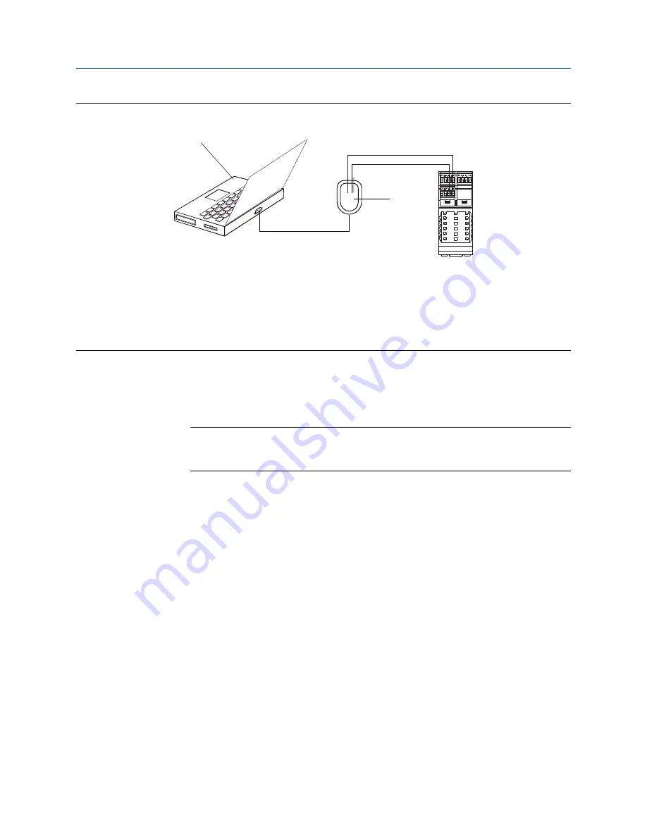
Connection to service port
Figure A-1:
A
B
C
A. PC
B. Signal converter
C. Transmitter
Note
This figure shows a serial port connection. USB connections are also supported.
4.
Start ProLink III.
5.
Choose Connect to Physical Device.
6.
Set Protocol to
Service Port
.
Tip
Service port connections use standard connection parameters and a standard address. You do
not need to configure them here.
7.
Set the PC Port value to the PC COM port that you are using for this connection.
8.
If required, power-cycle the transmitter to set the terminals to service port mode.
The transmitter terminals operate in either service port mode or RS-485 mode. If
they are in RS-485 mode, you must power-cycle the transmitter and connect within
the first 10 seconds. If you do not connect within 10 seconds, the terminals will
switch to RS-485 mode. If the terminals are already in service port mode, skip this
step.
9.
Click Connect.
Need help?
If an error message appears:
•
Switch the leads and try again.
•
Ensure that you have specified the correct port on your PC.
•
Check the wiring between the PC and the transmitter.
•
Ensure that the RS-485 terminals on the transmitter are in service port mode.
Using ProLink III with the transmitter
200
Micro Motion Model 2500 Transmitters with Configurable Input/Outputs
Summary of Contents for Micro Motion 2500
Page 8: ...Contents vi Micro Motion Model 2500 Transmitters with Configurable Input Outputs ...
Page 10: ...Getting started 2 Micro Motion Model 2500 Transmitters with Configurable Input Outputs ...
Page 18: ...Quick start 10 Micro Motion Model 2500 Transmitters with Configurable Input Outputs ...
Page 237: ...NE 53 history Configuration and Use Manual 229 ...


