Field Setting from Outdoor Unit
SiUS342303E
191
Part 5 Field Settings and Test Operation
25
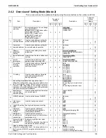
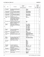
External low
noise level
Low noise level when the external
low noise signal is input at option
DTA104A62.
2.
2
5
Level 1
Level 2
Level 3
1
2
3
26
Automatic night-
time low noise
operation start
Time to start automatic “night-time
low noise” operation. (“Night-time
low noise” level setting should also
be made.)
2.
2
6
About 8:00 PM
About 10:00 PM
About 12:00 AM
1
2
3
27
Automatic night-
time low noise
operation stop
Time to stop automatic “night-time
low noise” operation. (“Night-time
low noise” level setting should also
be made.)
2.
2
7
About 6:00 AM
About 7:00 AM
About 8:00 AM
1
2
3
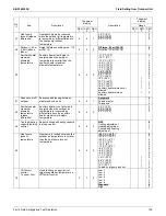
28
Power transistor
check
Used to troubleshoot DC
compressor. Inverter waveforms
are output without wire connections
to the compressor. It is useful to
determine whether the relevant
trouble has resulted from the
compressor or inverter PCB.
2.
2
8
OFF
ON (10 Hz)
0
1
29
Capacity priority Cancel the low noise level control if
capacity is required while low noise
operation or night-time low noise
operation is in progress.
2.
2
9
OFF
ON
0
1
30
Demand 1
setting
Used to make a change to the
targeted power consumption level
when the demand 1 control signal
is inputted.
2.
3
0
Level 1 (60%)
Level 2 (65%)
Level 3 (70%)
Level 4 (75%)
Level 5 (80%)
Level 6 (85%)
Level 7 (90%)
Level 8 (95%)
1
2
3
4
5
6
7
8
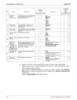
31
Demand 2
setting
Used to use a targeted power
current level when the demand 2
control signal is input.
2.
3
1
Level 1 (40%)
Level 2 (50%)
Level 3 (55%)
1
2
3
32
Normal demand
setting
Used to set permanent demand 1
or 2 control without inputting any
external signal.
2.
3
2
OFF
Demand 1 (2-30)
Demand 2 (2-31)
0
1
2
34
Indoor fan tap
setting
Indoor fan speed is limited to L tap
depending on connection capacity.
2.
3
4
Indoor capacity
≥
130%
Indoor capacity
≥
130% in
heating
Remote controller setting (Not
limited)
0
1
2
35
Height
difference
setting
In case the outdoor unit is installed
in the lowest position and the
height difference between the
highest indoor unit and the outdoor
unit exceeds 130 ft. (40 m),
2.
3
5
Level > 40 m (130 ft)
Level max. 40 m (130 ft)
0
1
37
Heat pump
lockout 2
Used for heat pump lockout
2.
3
7
OFF
Mode 1
Mode 2
Mode 3
Mode 4
Mode 5
Mode 6
0
1
2
3
4
5
6
38
Emergency
operation
(master)
To prohibit a compressor or
complete in “Master”. Since
module is permanent disabled,
immediately replace the defective
component(s).
2.
3
8
OFF
Master INV. 1 OFF
Master INV. 2 OFF
Master unit OFF
0
1
2
3
39
Emergency
operation (sub)
To prohibit a compressor or
complete “sub 1”. Since module is
permanent disabled, immediately
replace the defective
component(s).
2.
3
9
OFF
Sub INV. 1 OFF
Sub INV. 2 OFF
Sub unit OFF
0
1
2
3
42
Outdoor fan
Outdoor fan noise countermeasure
(limit fan speed).
2.
4
2
Standard
Mode A
Mode B
0
1
2
No.
1
Item
Description
7 segment
display
Description
7 segment
display
Range
SEG
1
SEG
2
SEG
3
SEG
1
SEG
2
SEG
3
Summary of Contents for VRV EMERION RXYQ-AATJA
Page 1: ...Service Manual Heat Pump 60 Hz RXYQ AATJA 208 230 V RXYQ AAYDA 460 V SiUS342303E...
Page 410: ...Wiring Diagrams SiUS342303E 403 Part 7 Appendix FXEQ07 09 12 15 18 24PVJU 3D098557A...
Page 411: ...SiUS342303E Wiring Diagrams Part 7 Appendix 404 FXDQ07 09 12 18 24MVJU C 3D050501C...
Page 416: ...Wiring Diagrams SiUS342303E 409 Part 7 Appendix FXHQ12 24 36MVJU 3D048116C...
Page 417: ...SiUS342303E Wiring Diagrams Part 7 Appendix 410 FXAQ07 09 12 18 24PVJU 3D075354F...
Page 424: ...Wiring Diagrams SiUS342303E 417 Part 7 Appendix VAM1200GVJU 3D073270D...


