


Field Setting from Outdoor Unit
SiUS342303E
189
Part 5 Field Settings and Test Operation
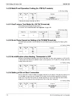
[1-9]:
shows the AIRNET address.
[1-10]:
shows the total number of connected indoor units.
It can be convenient to check if the total number of indoor units which are installed
match the total number of indoor units which are recognized by the system. In case
there is a mismatch, it is advised to check the communication wiring path between
outdoor and indoor units (F1/F2 communication line).
[1-13]:
shows the total number of connected outdoor units.
It can be convenient to check if the total number of outdoor units which are installed
matches the total number of outdoor units which are recognized by the system. In case
there is a mismatch, It is advised to check the communication wiring path between
outdoor and outdoor units (Q1/Q2 communication line).
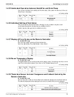
[1-15]:
shows number of units in zone.
[1-16]:
shows number of all indoor units of several systems if “F1F2 OUT/D" is wired between
systems. (Number of terminal units: represents the number of indoor units connected to
a single DIII-NET that is a communication line.)
[1-17]:
shows the latest error code.
[1-18]:
shows the 2nd last error code.
[1-19]:
shows the 3rd last error code.
When the latest error codes were reset by accident on an indoor unit user interface,
they can be checked again through this monitoring settings.
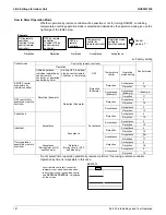
[1-28]:
shows number of outdoor units connected to a multi system.
[1-35]:
shows the latest prediction code.
[1-36]:
shows the 2nd last prediction code.
[1-37]:
shows the 3rd last prediction code.
[1-38]:
shows the number of Mini-split indoor units connected to the system.
[1-40]:
shows the current cooling comfort setting.
[1-41]:
shows the current heating comfort setting.
[1-42]:
shows the current high pressure sensor value (psi).
[1-43]:
shows the current low pressure sensor value (psi).
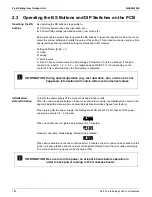
[1-46]:
shows the current compressor 1 discharge thermistor value (°F).
[1-48]:
shows the current compressor 1 body thermistor value (°F).
[1-49]:
shows the current outdoor air thermistor value (°F).
[1-50]:
shows the current compressor suction thermistor value (°F).
[1-51]:
shows the current subcooling gas thermistor value (°F).
[1-52]:
shows the current deicer thermistor value (°F). (Right side for 192-240 class)
[1-53]:
shows the compressor run time (hour divided by 100).
[1-54]:
shows the current heat exchanger liquid pipe thermistor value (°F). (Right side for
192-240 class)
[1-55]:
shows the current subcooling liquid thermistor value (°F).
[1-57]:
shows the current heat exchanger gas (left) thermistor value (°F). (Only for 192-240
class)
[1-58]:
shows the current deicer (left) thermistor value (°F). (Only for 192-240 class)
[1-59]:
shows the current heat exchanger liquid pipe (left) thermistor value (°F). (Only for
192-240 class)
[1-60]:
shows the current compressor 2 discharge thermistor value (°F).
[1-61]:
shows the current compressor 2 body thermistor value (°F).
[1-64]:
shows the compressor average load.
[1-65]:
shows the current electrical components box thermistor value (°F).
[1-66]:
shows the current cooling jacket outlet thermistor value (°F).
Summary of Contents for VRV EMERION RXYQ-AATJA
Page 1: ...Service Manual Heat Pump 60 Hz RXYQ AATJA 208 230 V RXYQ AAYDA 460 V SiUS342303E...
Page 410: ...Wiring Diagrams SiUS342303E 403 Part 7 Appendix FXEQ07 09 12 15 18 24PVJU 3D098557A...
Page 411: ...SiUS342303E Wiring Diagrams Part 7 Appendix 404 FXDQ07 09 12 18 24MVJU C 3D050501C...
Page 416: ...Wiring Diagrams SiUS342303E 409 Part 7 Appendix FXHQ12 24 36MVJU 3D048116C...
Page 417: ...SiUS342303E Wiring Diagrams Part 7 Appendix 410 FXAQ07 09 12 18 24PVJU 3D075354F...
Page 424: ...Wiring Diagrams SiUS342303E 417 Part 7 Appendix VAM1200GVJU 3D073270D...


