


SiUS342303E
Field Setting from Outdoor Unit
Part 5 Field Settings and Test Operation
184
2.2 Accessing the BS Buttons on the PCB
It is not required to open the complete electronic component box to access the BS buttons on the
PCB and read out the seven-segment display(s).
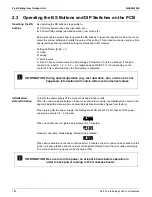
1.
Open the service window cover.
2.
Open the inspection door.
You can see the 3 BS buttons and the 3 seven-segment displays and DIP switches.
Operate the switches and BS buttons with an insulated stick (such as a closed ballpoint pen) to
avoid touching of live parts.
Location of the seven-segment displays, buttons and DIP switches:
Segment display indications:
1
2
BS1 BS2 BS3
DS1 DS2
X27A
1
2
MODE (BS1)
for changing setting mode
SET (BS2), RETURN (BS3)
DS1, DS2
DIP switches
1
Seven-segment displays (3×)
2
BS buttons (3×)
for changing field setting
Off
Blinking
On
Summary of Contents for VRV EMERION RXYQ-AATJA
Page 1: ...Service Manual Heat Pump 60 Hz RXYQ AATJA 208 230 V RXYQ AAYDA 460 V SiUS342303E...
Page 410: ...Wiring Diagrams SiUS342303E 403 Part 7 Appendix FXEQ07 09 12 15 18 24PVJU 3D098557A...
Page 411: ...SiUS342303E Wiring Diagrams Part 7 Appendix 404 FXDQ07 09 12 18 24MVJU C 3D050501C...
Page 416: ...Wiring Diagrams SiUS342303E 409 Part 7 Appendix FXHQ12 24 36MVJU 3D048116C...
Page 417: ...SiUS342303E Wiring Diagrams Part 7 Appendix 410 FXAQ07 09 12 18 24PVJU 3D075354F...
Page 424: ...Wiring Diagrams SiUS342303E 417 Part 7 Appendix VAM1200GVJU 3D073270D...


