MagnaTran 7.1 User’s Manual
Appendices
MN-003-1600-00
Appendix F: Relay I/O Option
Brooks Automation
Revision 2.2
11-27
This section provides the functions and hexadecimal representations for both the
inputs and outputs of the Relay I/O board (002-4212-01). These inputs and outputs
can be used for either of the following two aspects of the robot:
1) To utilize various robot operational interlocks.
2) To operate the robot under Digital I/O (DIO) control.
Reference
Discrete I/O Control (DIO) on page 6-45
for additional information per-
taining to both operational interlocks and DIO control.
The J1 connector of the Relay I/O board contains the INPUT pins for the robot. The
pin-outs, functions, and hexadecimal representations for the J1 connector are pre-
sented in the following table:
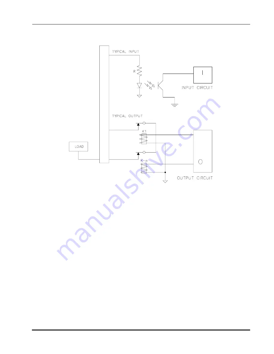
Figure 11-2: Relay I/O Circuit


