


3 Pump controller fields of application and layout
32
bplogic intelligent pump controller
18/02/2021
3.2.4.3
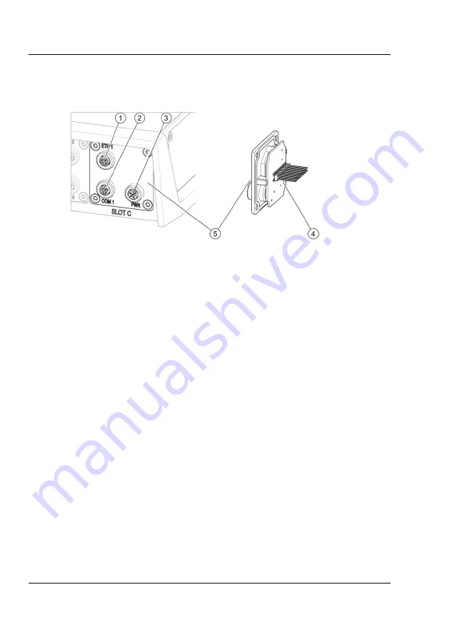
Slot C
Power module
F
ig
_
Sl
o
t
C
.svg
Fig. 8: Slot C
1
ETH 1: Ethernet or ethernet-based field bus
2
COM 1: Modbus RTU
3
PWR: 24 V power supply
4
Housing inside/contacts to main board
5
Housing outside/connections
The module in slot C contains the power supply connection (24 V DC, Fig. 8/3),
the ETH 1 ethernet connection (Fig. 8/1) and the modbus RTU connection
(COM 1, Fig. 8/2). Each of the connections is designed as an M12 socket.
The ETH 1 ethernet connection is intended to connect the pump controller
permanently to an ethernet network or a field bus.
The M12 socket can be used to establish the connection while retaining hous-
ing protection category IP65. In order to obtain the housing protection category,
the unused M12 connections must be sealed with the sealing caps provided.
The power supply (24 V DC) is established via the PWR connection (M12 con-
nection, Fig. 8/3) and feeds sensors and the main board galvanically separated
from the actuators, so that any overcurrent in the actuators does not cause the
logic and sensors to fail. If actuators with a high current requirement are to be
supplied, this can be performed by a second 24 V power supply.