


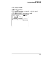


Verify the test signal
1
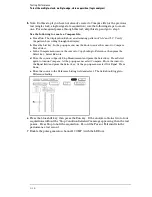
Check the clock period. Using the oscilloscope, verify that the master-to-master
clock time is 6.666 ns, +0 ps or – 100 ps.
a
Enable the pulse generator channel 1, channel 2, and trigger outputs (LED off).
b
In the oscilloscope Timebase menu, select Scale: 2.000 ns/div.
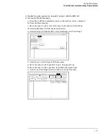
c
In the oscilloscope Timebase menu, select Position. Using the oscilloscope knob,
position the clock waveform so that a rising edge appears at the left of the display.
d
On the oscilloscope, select [Shift] + width: channel 2, then select [Enter] to display the
master-to-master clock time (+ width(2)). If the positive-going pulse width is more
than 6.666 ns, go to step d. If the positive-going pulse width is less than or equal to
6.666 ns but greater than 6.566 ns, go to step 2.
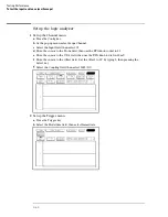
e
On the oscilloscope, select [Shift] - width: channel 2, then select [Enter] (- width(2)). If
the negative pulse width is less than or equal to 6.666 ns but greater than 6.566 ns, go
to step 2.
f
Decrease the pulse generator Period in 100 ps increments until the oscill
width (2) or - width (2) read less than or equal to 6.666 ns, but greater than 6.566 ns.
Testing Performance
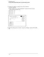
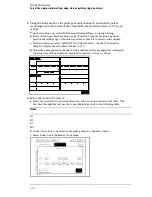
To test the single-clock, multiple-edge, state acquisition (logic analyzer)
3–47
Summary of Contents for 1670G Series
Page 20: ...1 12...
Page 116: ...Testing Performance Performance Test Record pattern generator 3 92...
Page 126: ...Calibrating and Adjusting To test the CAL OUTPUT ports 4 10...
Page 166: ...Exploded View of the Agilent 1670G series logic analyzer Replacing Assemblies 6 4...
Page 201: ...Theory of Operation The Oscilloscope Board 8 11...


