


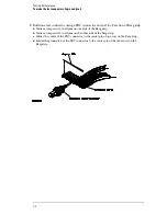


To make the test connectors (logic analyzer)
The test connectors connect the logic analyzer to the test equipment.
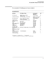
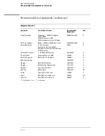
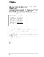
Materials Required
Description
Recommended Part
Qty
BNC (f) Connector
1250-1032
5
100
Ω
1% resistor
0698-7212
8
Berg Strip, 17-by-2
1
Berg Strip, 6-by-2
4
20:1 Probe
54006A
2
Jumper wire
1
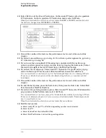
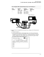
Build four test connectors using BNC connectors and 6-by-2 sections of Berg strip.
a
Solder a jumper wire to all pins on one side of the Berg strip.
b
Solder a jumper wire to all pins on the other side of the Berg strip.
c
Solder two resistors to the Berg strip, one at each end between the end pins.
d
Solder the center of the BNC connector to the center pin of one row on the Berg strip.
e
Solder the ground tab of the BNC connector to the center pin of the other row on the
Berg strip.
f
On two of the test connectors, solder a 20:1 probe. The probe ground goes to the
same row of pins on the test connector as the BNC ground tab.
3–7
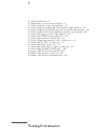
Summary of Contents for 1670G Series
Page 20: ...1 12...
Page 116: ...Testing Performance Performance Test Record pattern generator 3 92...
Page 126: ...Calibrating and Adjusting To test the CAL OUTPUT ports 4 10...
Page 166: ...Exploded View of the Agilent 1670G series logic analyzer Replacing Assemblies 6 4...
Page 201: ...Theory of Operation The Oscilloscope Board 8 11...


