


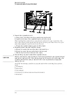


To remove and replace the disk drive assembly
1
Using previous procedures, remove the following assemblies:
•
Handle
•
Rear Feet
•
Cover
2
Disconnect the two disk-drive ribbon cables from the CPU board. Peel the cables
away from the double-sided tape used to secure the cables to the disk drive bracket.
3
Remove the two screws that attach the disk drive bracket to the support tray.
4
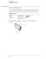
Slide the disk drive assembly toward the front of the instrument about 1/2 inch
(1.25 cm). Angle the rear of the bracket up and out of the chassis. Then remove the
disk drive assembly completely out of the chassis by sliding the assembly toward the
rear of the instrument.
5
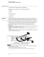
If needed, remove the support tray from the chassis.
a. Lift the PCB locking pins out of the chassis.
b. Slide the support tray out of the second slot of the chassis.
When installing the support tray, ensure that the tabs on the support tray are inserted into the
slots in the handle plate.
6
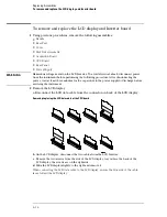
Remove the flexible disk drive from the bracket.
a. Disconnect the flexible disk drive from the bracket.
b. Remove the four screws that attach the flexible disk drive to the bracket. There
are two on each side.
c. Lift the flexible disk drive out of the bracket.
d. To remove the interface board, remove one screw that attaches the interface
board to the bracket and lift the board out of the bracket.
7
Remove the hard disk drive from the bracket.
a. Disconnect the hard disk drive cable from the hard disk drive.
When connecting the cable, ensure the cable is connected to the Data pins, not the
Address pins.
b. Remove the four screws on the top of the bracket that attach the hard drive to the
bracket.
c. Lift the hard disk drive out of the bracket.
Replacing Assemblies
To remove and replace the disk drive assembly
6–6
Summary of Contents for 1670G Series
Page 20: ...1 12...
Page 116: ...Testing Performance Performance Test Record pattern generator 3 92...
Page 126: ...Calibrating and Adjusting To test the CAL OUTPUT ports 4 10...
Page 166: ...Exploded View of the Agilent 1670G series logic analyzer Replacing Assemblies 6 4...
Page 201: ...Theory of Operation The Oscilloscope Board 8 11...


