


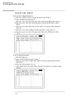

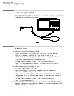


Set up the logic analyzer
1
1
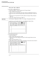
Set up the Configuration menu.
a
Press the Config key. At the pop up menu, select Scope Channel.
b
Select the Input field, then select C1.
c
Move the cursor to the Probe field, press Select, then use the RPG knob to dial in 1:1.
d
Move the cursor to the V/Div field, press Select, then use the PRG knob to dial in
400 mV.
e
Move the cursor to the Offset field. Set the offset to 0 by typing 0, then pressing the
Select key.
f
Move the cursor to the Coupling field, then press Select. Select 50
Ω
/ DC.
g
Move the cursor to the s/Div field, press Select, then use the RPG knob to dial in
5.00 ns.
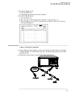
2
Set up the Display menu.
a
Press the Display key.
b
Select the Mode field, then select Average.
c
Move the cursor to the Average # field. Enter "8" in the front-panel keyboard, then
press Done.
d
Select the Grid field and set it to On.
e
In the Waveform selection menu, delete channel 2. If channel 1 is not inserted, insert
channel 1.
Testing Performance
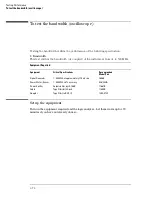
To test the trigger sensitivity (oscilloscope)
3–82
Summary of Contents for 1670G Series
Page 20: ...1 12...
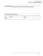
Page 116: ...Testing Performance Performance Test Record pattern generator 3 92...
Page 126: ...Calibrating and Adjusting To test the CAL OUTPUT ports 4 10...
Page 166: ...Exploded View of the Agilent 1670G series logic analyzer Replacing Assemblies 6 4...
Page 201: ...Theory of Operation The Oscilloscope Board 8 11...


