


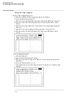


Acquire the data
1
Obtain the 1 MHz response.
a
Set the signal generator for 1 MHz at
−
2.4 dBm.
b
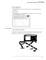
Press the blue shift key, then press the Run key. The signal on the screen should be
two cycles at three divisions amplitude. After approximately 15 seconds (averaging
complete), press the Stop key.
c
Press the Meas key. Note the voltage reading in the V
p-p
field.
V
1 MHz
= __________ mV.
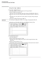
2
Set the signal generator for 500 MHz frequency.
a
Set the power meter Cal Factor % to the 1 MHz value from the calibration chart on the
power splitter. Press dB[REF] to set a 0 dB reference.
b
Change the signal generator frequency to 500 MHz. Set the power meter Cal Factor %
to the 500 MHz value from the chart.
c
Adjust the signal generator amplitude for a power reading as close as possible to 0.0
dB[REL] and note the power reading. Reading = __________ dB.
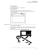
3
Obtain the 500 MHz response.
a
Use the RPG knob to dial in a s/Div value of 1 ns/Div.
b
Press the blue shift key, then press the Run key. After approximately 15 seconds
(averaging complete), press the Stop key.
c
Note the voltage reading in the V
p-p
field V
500MHz
= ________mV.
4
Determine the oscilloscope response.
a
Calculate the response using the formula:
response
(
dB
)
=
20 log
10
V
500
Mhz
V
1
MHz
=
20log
10
(
_____
)
=
______
dB
b
Correct the result from step 4a above with any differences in the power meter from
step 2c. Observe signs. For example:
Result from step 4a =
−
2.3 dB
Power meter reading =
−
0.2 dB[REL]
then true response = (
−
2.3)
−
(
−
0.2)
= −
2.1dB
(__________)
−
(__________) = ____________ dB
c
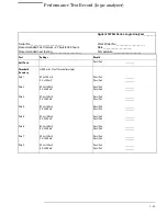
The result from step 4b should be
≤
−
3.0 dB. Record the result in the performance test
record.
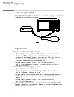
5
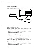
Remove the power splitter from the oscilloscope channel 1 input and connect it to
the channel 2 input.
6
Repeat from "Set up the logic analyzer" for channel 2, replacing channel 1 with
channel 2 where applicable.
See Also
Failure of the bandwidth test can be caused by a faulty attenuator or main assembly (see
chapter 6).
Testing Performance
To test the bandwidth (oscilloscope)
3–76
Summary of Contents for 1670G Series
Page 20: ...1 12...
Page 116: ...Testing Performance Performance Test Record pattern generator 3 92...
Page 126: ...Calibrating and Adjusting To test the CAL OUTPUT ports 4 10...
Page 166: ...Exploded View of the Agilent 1670G series logic analyzer Replacing Assemblies 6 4...
Page 201: ...Theory of Operation The Oscilloscope Board 8 11...


