


6
Allow the keyboard assembly to fall forward from the front panel. Separate the
elastomeric keypad and keyboard panel from the PC board.
7
Using a paper clip or screwdriver, short the PC board trace of the non-operating key
and look for an appropriate response on the display.
8
If the display responds as though the key was pressed, replace the elastomeric
keypad.
If the display does not respond as though the key was pressed, replace the keyboard.
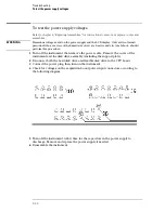
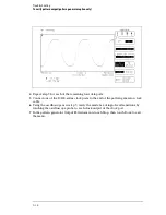
9
Check the RPG connector.
The RPG connector has a TTL pulse on pins 22 and 24 when you turn the knob. Pin 20 of the
connector is +5 V.
Troubleshooting
To test the keyboard signals
5–23
Summary of Contents for 1670G Series
Page 20: ...1 12...
Page 116: ...Testing Performance Performance Test Record pattern generator 3 92...
Page 126: ...Calibrating and Adjusting To test the CAL OUTPUT ports 4 10...
Page 166: ...Exploded View of the Agilent 1670G series logic analyzer Replacing Assemblies 6 4...
Page 201: ...Theory of Operation The Oscilloscope Board 8 11...


