


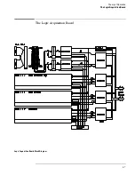


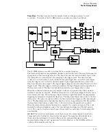


GPIB Interface
The instrument interfaces to GPIB as defined by IEEE Standard 488.2. The interface consists
of an GPIB controller and two octal drivers/receivers. The microprocessor routes GPIB data
to the controller. The controller then buffers the 8-bit GPIB data bits and generates the bus
handshaking signals. The data and handshaking signals are then routed to the GPIB bus
through the octal line drivers/receivers. The drivers/receivers provide data and control signal
transfer between the bus and controller.
RS-232-C Interface
The instrument RS-232-C interface is compatible with standard RS-232-C protocol. The
interface consists of a controller, and drivers/receivers. The controller serializes parallel data
from the microprocessor for transmission. At the same time the controller also receives serial
data and converts the data to parallel data characters for the microprocessor.
The controller contains a baud rate generator that can be programmed from the logic analyzer
front panel for one of eight baud rates. Other RS-232-C communications parameters can also
be programmed from the logic analyzer front panel.
The drivers/receivers interface the instrument with data communications equipment. Slew
rate control is provided on the ICs eliminating the need for external capacitors.
LCD Display Assembly
The LCD display is a Mitsubishi 8.4-inch industrial-quality TFT active display. 6 bits of display
data from the CPU board result in a 640x480 VGA resolution at the display.
Flexible Disk Drive
The disk drive assembly is a high density disk drive that formats double-sided, double-density
or high-density disks in LIF or DOS format. A disk drive controller on the CPU board controls
the disk drive. Signals are routed directly to the disk drive through the disk drive cable.
Power Supply
A low voltage power supply provides all dc voltages needed to operate the logic analyzer. The
power supply also provides the +5 Vdc voltage to the probe cables to power logic analyzer
accessories and analysis probes.
Unfiltered voltages of +12 V, -12 V, +5 V, -5.2 V, and +3.5 V are supplied to the acquisition
board where they are filtered and distributed to the CPU board, CRT Monitor Assembly, and
probe cables.
Centronics Interface
The interface to the Centronics port includes latches and buffers. The latches and buffers
convert the logic analyzer backplane signals into parallel Centronics signals.
Theory of Operation
The Agilent 1670G-Series Logic Analyzer
8–5
Summary of Contents for 1670G Series
Page 20: ...1 12...
Page 116: ...Testing Performance Performance Test Record pattern generator 3 92...
Page 126: ...Calibrating and Adjusting To test the CAL OUTPUT ports 4 10...
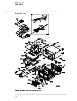
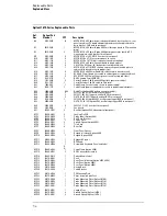
Page 166: ...Exploded View of the Agilent 1670G series logic analyzer Replacing Assemblies 6 4...
Page 201: ...Theory of Operation The Oscilloscope Board 8 11...


