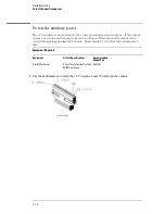


To remove and replace pattern generator board ( pattern
generator option only)
1
Using previous procedures, remove the following assemblies:
•
Handle
•
Rear Feet
•
Cover
•
Rear Panel
•
Disk Drive Assembly
•
Acquisition Board
•
Power Supply
2
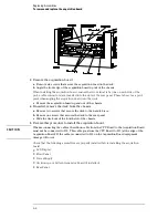
Slide the mounting plate out the rear of the instrument.
Verify that the cable release tabs are down to slide the mounting plate out, then slide the
mounting plate toward the rear out of the chassis.
3
Separate the pattern generator board from the mounting plate by removing the
screw at the center of the board. Remove the pattern generator-to-acquisition board
cable.
a
Disconnect the acquisition board-pattern generator board interface cable from the
pattern generator board. To do this press down on the cable release tabs on the cable
socket located on the board.
b
Remove the screw at the center of the pattern generator board that secures the board
to the mounting plate.
c
Slide the board approximately 0.5 cm and lift the board off the mounting plate.
4
Reverse this procedure to install the pattern generator board.
When installing the mounting plate, check that the alignment tabs on the mounting plate are
installed in the alignment holes in the inside bottom, front of the chassis.
Replacing Assemblies
To remove and replace pattern generator board ( pattern generator option only)
6–14
Summary of Contents for 1670G Series
Page 20: ...1 12...
Page 116: ...Testing Performance Performance Test Record pattern generator 3 92...
Page 126: ...Calibrating and Adjusting To test the CAL OUTPUT ports 4 10...
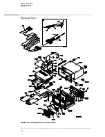
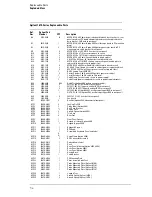
Page 166: ...Exploded View of the Agilent 1670G series logic analyzer Replacing Assemblies 6 4...
Page 201: ...Theory of Operation The Oscilloscope Board 8 11...


