
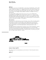


GPIB
The Agilent Technologies Interface bus (GPIB) is Agilent Technologies’
implementation of IEEE Standard 488-1978, "Standard Digital Interface for
Programming Instrumentation." GPIB is a carefully defined interface that simplifies
the integration of various instruments and computers into systems. The interface
makes it possible to transfer messages between two or more GPIB compatible
devices. GPIB is a parallel bus of 16 active signal lines divided into three functional
groups according to function.
Eight signal lines, called data lines, are in the first functional group. The data lines
are used to transmit data in coded messages. These messages are used to program
the instrument function, transfer measurement data, and coordinate instrument
operation. Input and output of all messages, in bit parallel-byte serial form, are also
transferred on the data lines. A 7-bit ASCII code normally represents each piece of
data.
Data is transferred by means of an interlocking "Handshake" technique which permits
data transfer (asynchronously) at the rate of the slowest active device used in that
transfer. The data byte control lines coordinate the handshaking and form the
second functional group.
The remaining five general interface management lines (third functional group) are
used to manage the devices connected to the GPIB. This includes activating all
connected devices at once, clearing the interface, and other operations.
Theory of Operation
GPIB
8–30
Summary of Contents for 1670G Series
Page 20: ...1 12...
Page 116: ...Testing Performance Performance Test Record pattern generator 3 92...
Page 126: ...Calibrating and Adjusting To test the CAL OUTPUT ports 4 10...
Page 166: ...Exploded View of the Agilent 1670G series logic analyzer Replacing Assemblies 6 4...
Page 201: ...Theory of Operation The Oscilloscope Board 8 11...


