


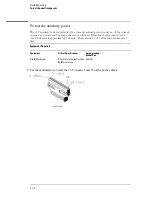


To test the logic analyzer probe cables
This test allows you to functionally verify the probe cable and probe tip assembly of any of the
logic analyzer pods. Only one probe cable can be tested at a time. Repeat this test for each
probe cable to be tested.
Equipment Required
Equipment
Critical Specification
Recommended
Model/Part
Pulse Generator
100 MHz, 3.5 ns pulse width,
< 600 ps rise time
8133A Option 003
Adapter (Qty 4)
SMA (m) - BNC (f)
1250-1200
Coupler (Qty 4)
BNC (m)(m)
1250-0216
6x2 Test Connectors (Qty 4)
1
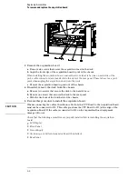
Turn on the equipment and the logic analyzer.
2
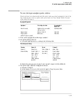
Set up the pulse generator.
a
Set up the pulse generator according to the following table.
Pulse Generator Setup
Timebase
Channel 2
Period
Channel 1
Mode: Int
Mode: Pulse
Divide: Divide
÷
1
Mode: Pulse
Period: 20.000 ns
Divide: PULSE
÷
1
Ampl: 0.50 V
Delay: 0.000 ns
Width: 3.500 ns
Offs: 0.00 V
Width: 3.500 ns
High:
−
0.90 V
High:
−
0.90 V
Low:
−
1.70 V
Low:
−
1.70 V
COMP: Disabled
(LED Off)
COMP: Disabled
(LED Off)
b
Enable the pulse generator channel 1 and channel 2 outputs (with the LEDs off).
3
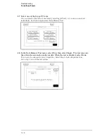
Set up the logic analyzer Configuration menu.
a
Press the Config key.
b
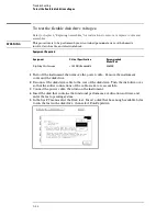
In the Analyzer 1 box, select the field to the right of Type, then select State.
Troubleshooting
To test the logic analyzer probe cables
5–29
Summary of Contents for 1670G Series
Page 20: ...1 12...
Page 116: ...Testing Performance Performance Test Record pattern generator 3 92...
Page 126: ...Calibrating and Adjusting To test the CAL OUTPUT ports 4 10...
Page 166: ...Exploded View of the Agilent 1670G series logic analyzer Replacing Assemblies 6 4...
Page 201: ...Theory of Operation The Oscilloscope Board 8 11...


