

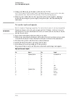


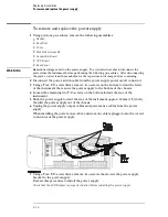

To verify pattern output (pattern generator option only)
Equipment Required
Equipment
Critical Specification
Recommended Model/Part
Oscilloscope
≥
500 MHz Bandwidth
54522A
Probe
500 MHz Bandwidth
10441A
Output Data Pod
no substitute
10460A - series
1
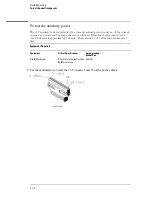
Connect one of the 10460-series data pods to the end of the pattern generator Pod 1
cable.
2
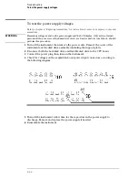
Touch Output Patterns. In the pop-up menu, touch Checkerboard Pattern.
3
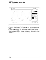
Using an oscilloscope, verify the existence of logic-level transitions by touching the
oscilloscope probe to each channel of Data Pod 1 and doing an Autoscale. The signal
levels that appear on the oscilloscope display should correspond with the logic
levels represented by the 10460-series pod being used.
Troubleshooting
To verify pattern output (pattern generator option only)
5–33
Summary of Contents for 1670G Series
Page 20: ...1 12...
Page 116: ...Testing Performance Performance Test Record pattern generator 3 92...
Page 126: ...Calibrating and Adjusting To test the CAL OUTPUT ports 4 10...
Page 166: ...Exploded View of the Agilent 1670G series logic analyzer Replacing Assemblies 6 4...
Page 201: ...Theory of Operation The Oscilloscope Board 8 11...


