


Oscilloscope tests (Scope PV)
The following self-tests check the major components of the Agilent 1670G-series oscilloscope
board as well as all associated circuitry (you must have the oscilloscope option). When the
self-tests have all been completed with a "PASS" status, the major data and control pipelines
in the Agilent 1670G-series oscilloscope board are functioning properly.
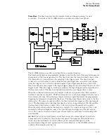
Data Memory Test
This test verifies the correct operation of the FISO
(fast-in/slow-out) data memory on the board. Test patterns are written into the memory
and then read and compared with known values.
Timebase Test
The pre-trigger and post-trigger delay modes are first tested by
programming a predetermined time interval in the trigger counters. At the end of the
time intervals, the arm, trigger, and run status bits are read and compared with known
values. The coarse and fine interpolators are then checked by reading the values of the
interpolator counters after a simulated acquisition. The counter values are then
compared with a known value. Finally, the sample clock is checked by programming a
sample clock frequency and then reading the status of the clock to detect when one clock
period has elapsed. The clock period time interval is then compared with a known value.
A/D Test
This test verifies the correct operation of the A/D converter on the board. A
check of the trigger in Trigger Immediate mode is first made. The A/D converters are then
exercised by setting the reference voltage and channel offset such that a simulated
acquisition obtains data in the extremes and middle of the quantization range of the A/D
converter. After each simulated acquisition, the data is compared with known values.
D/A Test
This test verifies the correct operation of the D/A converter on the board.
Both the offset and trigger level D/A converters for each channel are set to a reference
level and then changed. The logic trigger IC is programmed to detect the changes. The
detection of a correct trigger indicates that the D/A converter is operating normally.
Trigger Test
This test verifies the correct operation of the trigger components on the
board. First, the logic trigger memory is checked by writing and then reading known
patterns. The logic qualifiers, logic trigger output, and trigger holdoff are then checked.
IMB Test
This test verifies the correct operation of the oscilloscope board interface to
the intermodule bus.
All Tests
This will automatically execute each test, one at a time, until all tests are
done.
Theory of Operation
Oscilloscope tests (Scope PV)
8–25
Summary of Contents for 1670G Series
Page 20: ...1 12...
Page 116: ...Testing Performance Performance Test Record pattern generator 3 92...
Page 126: ...Calibrating and Adjusting To test the CAL OUTPUT ports 4 10...
Page 166: ...Exploded View of the Agilent 1670G series logic analyzer Replacing Assemblies 6 4...
Page 201: ...Theory of Operation The Oscilloscope Board 8 11...


