


2
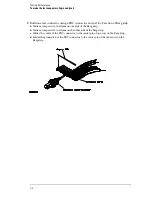
Build one test connector using a BNC connector and a 17-by-2 section of Berg strip.
a
Solder a jumper wire to all pins on one side of the Berg strip.
b
Solder a jumper wire to all pins on the other side of the Berg strip.
c
Solder the center of the BNC connector to the center pin of one row on the Berg strip.
d
Solder the ground tab of the BNC connector to the center pin of the other row on the
Berg strip.
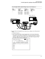
Testing Performance
To make the test connectors (logic analyzer)
3–8
Summary of Contents for 1670G Series
Page 20: ...1 12...
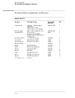
Page 116: ...Testing Performance Performance Test Record pattern generator 3 92...
Page 126: ...Calibrating and Adjusting To test the CAL OUTPUT ports 4 10...
Page 166: ...Exploded View of the Agilent 1670G series logic analyzer Replacing Assemblies 6 4...
Page 201: ...Theory of Operation The Oscilloscope Board 8 11...


