


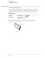


7
Using four 6-by-2 test connectors, four BNC Couplers, and four SMA (m) - BNC (f)
Adapters, connect the logic analyzer to the pulse generator channel outputs. To
make the test connectors, see chapter 3, "Testing Performance."
a
Connect the even-numbered channels of the lower byte of the pod under test to the
pulse generator channel 1 Output and J-clock.
b
Connect the odd-numbered channels of the lower byte of the pod under test to the
pulse generator channel 1 Output.
c
Connect the even-numbered channels of the upper byte of the pod under test and the
clock channel to the pulse generator channel 2 Output.
d
Connect the odd-numbered channels of the upper byte of the pod under test to the
pulse generator channel 2 Output.
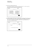
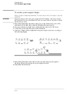
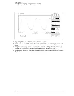
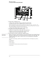
8
On the logic analyzer, press Run. The display should look similar to the figure below.
9
If the display looks like the figure, then the cable passed the test.
If the display does not look similar to the figure, then there is a possible problem
with the cable or probe tip assembly. Causes for cable test failures include the
following:
•
open channel
•
channel shorted to a neighboring channel
•
channel shorted to either ground or a supply voltage
Return to Troubleshooting Flowchart 7.
Troubleshooting
To test the logic analyzer probe cables
5–32
Summary of Contents for 1670G Series
Page 20: ...1 12...
Page 116: ...Testing Performance Performance Test Record pattern generator 3 92...
Page 126: ...Calibrating and Adjusting To test the CAL OUTPUT ports 4 10...
Page 166: ...Exploded View of the Agilent 1670G series logic analyzer Replacing Assemblies 6 4...
Page 201: ...Theory of Operation The Oscilloscope Board 8 11...


