


To perform the BNC test
Equipment Required
Equipment
Critical Specification
Recommended
Model/Part
Digitizing Oscilloscope
100 MHz Bandwidth
54820A
BNC Shorting Cap
1250-0774
BNC Cable
8120-1840
BNC-Banana Adapter
1251-2277
1
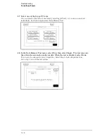
Press the Config key.
2
Assign pods 1 and 2 to Machine 1.
To assign the pod field, select the pods 1 and 2 field, then select Machine 1 in the pop-up
menu.
3
In the Analyzer 1 box, select the Type field. Select Timing in the pop-up menu.
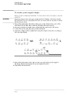
4
Set up the trigger menu.
a
Press the Trig key. Select Clear Trigger All.
b
Select Arming Control. In the Arming Control pop-up menu, select the field labeled
Run, then select Port In. Press the Done key.
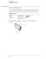
5
Attach a BNC shorting cap to the External Trigger Input on the rear panel of the
logic analyzer.
6
Using a BNC cable, connect the External Trigger output to the oscilloscope
channel 1 input. Set the oscilloscope to Trigger On and measure TTL voltage levels.
7
Press the RUN front-panel key.
The warning "MACHINE 1 Waiting on level 1" will appear.
8
Remove the shorting cap from the rear-panel External Trigger input BNC.
9
The warning will go away and the oscilloscope will display a positive-going TTL
pulse.
Troubleshooting
To perform the BNC test
5–28
Summary of Contents for 1670G Series
Page 20: ...1 12...
Page 116: ...Testing Performance Performance Test Record pattern generator 3 92...
Page 126: ...Calibrating and Adjusting To test the CAL OUTPUT ports 4 10...
Page 166: ...Exploded View of the Agilent 1670G series logic analyzer Replacing Assemblies 6 4...
Page 201: ...Theory of Operation The Oscilloscope Board 8 11...


