


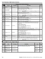


No.
(Addr.
Hex)
Name
LCD Display
Description
Values
Page
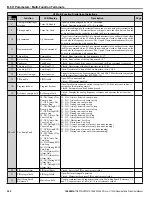
H3-09
(0417)
Terminal A2 Signal
Level Selection
Term A2 Level
0: 0 to 10 V
1: -10 to 10 V
2: 4 to 20 mA
3: 0 to 20 mA
Note:
Use DIP switch S1 to set input terminal A2 for a
current or a voltage input signal.
Default: 2
Range: 0 to 3
H3-10
(0418)
Terminal A2 Function
Selection
Term A2 FuncSel
Sets the function of terminal A2.
Default: B
Range: 0 to 28
H3-11
(0419)
Terminal A2 Gain
Setting
Terminal A2 Gain
Sets the level of the input value selected in H3-10 when 10 V
(20 mA) is input at terminal A2.
Default: 100.0%
Min.: -999.9
Max.: 999.9
H3-12
(041A) Terminal A2 Bias
Setting
Terminal A2 Bias
Sets the level of the input value selected in H3-10 when 0 V (0
or 4 mA) is input at terminal A2.
Default: 0.0%
Min.: -999.9
Max.: 999.9
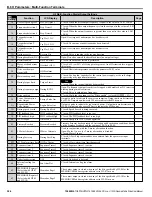
H3-13
(041B)
Analog Input Filter
Time Constant
A1/A2 Filter T
Sets a primary delay filter time constant for terminals A1, A2,
and A3. Used for noise filtering.
Default: 0.03 s
Min.: 0.00
Max.: 2.00
–
H3-14
(041C)
Analog Input Terminal
Enable Selection
A1/A2/A3 Sel
1: A1 Available
2: A2 Available
3: A1/A2 Available
4: A3 Available
5: A1/A3 Available
6: A2/A3 Available
7: All Available
Determines which analog input terminals will be enabled or
disabled when a digital input programmed for “Analog input
enable” (H1-
oo
= C) is activated.
The terminals not set as the target are not influenced by input
signals.
1: Terminal A1 only
2: Terminal A2 only
3: Terminals A1 and A2 only
4: Terminal A3 only
5: Terminals A1 and A3
6: Terminals A2 and A3
7: All terminals enabled
Default: 7
Range: 1 to 7
–
H3-16
(02F0) Terminal A1 Offset
TerminalA1Offset
Adds an offset when the analog signal to terminal A1 is at 0 V.
Default: 0
Min.: -500
Max.: 500
–
H3-17
(02F1) Terminal A2 Offset
TerminalA2Offset
Adds an offset when the analog signal to terminal A2 is at 0 V.
Default: 0
Min.: -500
Max.: 500
–
H3-18
(02F2) Terminal A3 Offset
TerminalA3Offset
Adds an offset when the analog signal to terminal A3 is at 0 V.
Default: 0
Min.: -500
Max.: 500
–
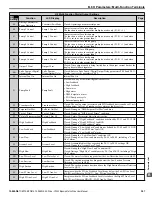
H3 Multi-Function Analog Input Settings
H3-
oo
Setting
Function
LCD Display
Description When Output Is 100%
Page
0
Frequency bias
Freq Ref Bias
E1-04 (maximum output frequency)
–
1
Frequency gain
Freq Ref Gain
0 to 10 V signal allows a setting of 0 to 100%. -10 to 0 V signal allows a setting
of -100 to 0%.
–
2
Auxiliary frequency
reference 1
Aux Reference1
E1-04 (maximum output frequency)
–
3
Auxiliary frequency
reference 2
Aux Reference2
E1-04 (maximum output frequency)
–
4
Output voltage bias
Voltage Bias
10 V = E1-05 (motor rated voltage)
–
5
Accel/decel time gain
Acc/DecTime Gain
10 V = 100%
–
6
DC Injection Braking
current
DC Brake Current
10 V = Drive rated current
–
7
Torque detection level
Torque Det Level
10 V = Drive rated current (V/f)
10 V = Motor rated torque (OLV)
–
8
Stall Prevention level
during run
Stall Prev Level
10 V = Drive rated current
–
9
Output frequency lower
limit level
Ref Lower Limit
10 V = E1-04 (maximum output frequency)
–
B
PID feedback
PID Feedback1
10 V = 100%
–
C
PID setpoint
PID Set Point
10 V = 100%
–
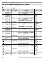
B.8 H Parameters: Multi-Function Terminals
YASKAWA TOEPYAIUPW01A YASKAWA AC Drive - U1000 iQpump Matrix Drive User Manual
309
B
Parameter List


