

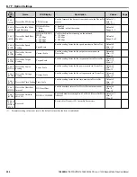


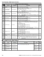


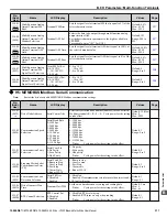


H2 Multi-Function Digital Output Settings
H2-
oo
Setting
Function
LCD Display
Description
Page
A0
Water Loss/Suction
Pressure/PI Aux Control WL/SP/PIAux Ctrl
Closed when the Water Level, Suction Pressure, or PI Auxiliary Controller is
affecting the output speed.
–
A1
Differential Detected
Differential Det
Closed: The difference between the PID Feedback and the Differential Feedback
(H3-
oo
= 28) exceeded the P4-18 level for the time set in P4-19.
–
A2
Sleep Active
Sleep Active
Closed: The drive is not running due to the Sleep function (does not include Sleep
Boost).
–
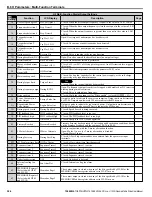
A3
Start Delay
Start Delay
Closed: Feedback has risen above the start level (or fallen below for Inverse PID)
and the start timer is timing.
–
A4
Pre-Charge
Pre-Chg Active
Closed: Drive is in Pre-Charge mode.
–
A5
Anti-Jam Active
Anti-Jam Active
Closed: The anti-jam function is active (configured by P7-
oo
).
–
A6
De-Scale Active
De-Scale Active
Closed: De-scale is running.
–
A7
Flow Rate Limit
Flow Rate Limit
Closed: The Flow Rate is actively affecting the output speed.
–
A9
Thrust Mode
Thrust Mode
Closed: The Thrust Bearing feature is active (output frequency is between 0 and
the value of P4-12).
–
AA
Utility Start Delay
Utility Delay
Closed: The drive is stopped and waiting for the utility delay timer set in P4-17 to
expire.
–
AB
Main Feedback Lost
Main FdBk Lost
Closed: Main feedback is lost.
–
AC
Backup Feedback Lost Backup FdBk Lost
Closed: Backup feedback is lost.
–
100 to
1AC
Function 0 to AC with
inverse output
!Function
Inverts the output switching of the multi-function output functions.
Set the last two digits of 1
oo
to reverse the output signal of that specific function.
–
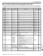
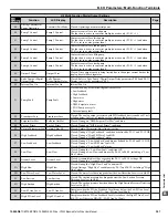
u
H3: Multi-Function Analog Inputs
No.
(Addr.
Hex)
Name
LCD Display
Description
Values
Page
H3-01
(0410)
Terminal A1 Signal
Level Selection
Term A1 Level
0: 0-10V,
(LowLim=0)
1: 0-10V, (BipolRef)
2: 4-20 mA
3: 0-20 mA
0: 0 to 10 V
1: -10 to 10 V
2: 4 to 20 mA
3: 0 to 20 mA
Note:
Use Jumper S1 to set input terminal A1 for a
current or voltage input signal.
Default: 0
Range: 0 to 3
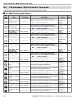
H3-02
(0434)
Terminal A1 Function
Selection
Term A1 FuncSel
Sets the function of terminal A1.
Default: 0
Range: 0 to 28
H3-03
(0411)
Terminal A1 Gain
Setting
Terminal A1 Gain
Sets the level of the input value selected in H3-02 when 10 V
is input at terminal A1.
Default: 100.0%
Min.: -999.9
Max.: 999.9
H3-04
(0412)
Terminal A1 Bias
Setting
Terminal A1 Bias
Sets the level of the input value selected in H3-02 when 0 V is
input at terminal A1.
Default: 0.0%
Min.: -999.9
Max.: 999.9
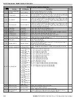
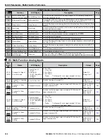
H3-05
(0413)
Terminal A3 Signal
Level Selection
Term A3 Signal
0: 0-10V (LowLim=0)
1: 0-10V, (BipolRef)
2: 4-20 mA
3: 0-20 mA
0: 0 to 10 V
1: -10 to 10 V
2: 4 to 20 mA
3: 0 to 20 mA
Note:
Use Jumper S1 to set input terminal A3 for a
current or voltage input signal.
Default: 0
Range: 0 to 3
H3-06
(0414)
Terminal A3 Function
Selection
Terminal A3 Sel
Sets the function of terminal A3.
Default: 20
Range: 0 to 28
H3-07
(0415)
Terminal A3 Gain
Setting
Terminal A3 Gain
Sets the level of the input value selected in H3-06 when 10 V
is input at terminal A3.
Default: 100.0%
Min.: -999.9
Max.: 999.9
H3-08
(0416)
Terminal A3 Bias
Setting
Terminal A3 Bias
Sets the level of the input value selected in H3-06 when 0 V is
input at terminal A3.
Default: 0.0%
Min.: -999.9
Max.: 999.9
B.8 H Parameters: Multi-Function Terminals
308
YASKAWA TOEPYAIUPW01A YASKAWA AC Drive - U1000 iQpump Matrix Drive User Manual


