10.6 MEMOBUS/Modbus Communications
YASKAWA
SIEPYAIH6B01A HV600 AC Drive Bypass Technical Reference
749
Table 10.29 Types of Enter Commands
Register No.
(Hex.)
Description
0900
When you write parameter data to the EEPROM, you will enable the data on the RAM at the same time.
This process saves the parameter changes even if you de-energize the drive.
0910
This updates the data on the RAM, but does not write data to the EEPROM.
If you de-energize the drive, you will lose the parameter changes.
Note:
•
You can write the EEPROM to the drive a maximum of 100,000 times. Do not frequently execute the Enter command (0900 (Hex.)) that is
written to EEPROM.
•
The Enter command register is write-only. If this register is read, it will cause a Register Number Error (02 (Hex.)).
•
When the command data or broadcast message is transmitted to the drive, the Enter command is not necessary.
■
Automatic Enter Command
The drive can be set up to automatically perform an Enter command after a parameter is written. Parameter
H5-11
enables and disables this feature.
◆
Self-Diagnostics
The bypass can use Self-Diagnostics to verify the hardware transceiver on the control circuit. Self-Diagnostics
connects the transmission terminal to the reception terminal on the control circuit and transmits the data to itself to
makes sure that the bypass can communicate correctly.
Use this procedure to do Self-Diagnostics:
DANGER!
Electrical Shock Hazard. Do not examine, connect, or disconnect wiring on an energized bypass. Before servicing,
disconnect all power to the equipment and wait for the time specified on the warning label at a minimum. The internal capacitor
stays charged after the bypass is de-energized. The charge indicator LED extinguishes when the DC bus voltage decreases below
50 Vdc. When all indicators are OFF, remove the covers before measuring for dangerous voltages to make sure that the bypass is
safe. If you do work on the bypass when it is energized, it will cause serious injury or death from electrical shock.
1.
Energize the bypass.
2.
Set
Z2-06 = 45 [Digital Input 6 Function (TB2-6) - Serial Hardware Test (RS-485)]
.
3.
De-energize the bypass.
4.
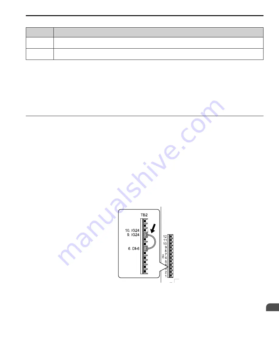
Connect a jumper between control circuit terminals TB2-6 and TB2-9 or TB2-10.
Figure 10.24 Self-Diagnostics Jumper Terminals
5.
Energize the bypass.
6.
When normal, the keypad will show
PASS [Serial Communication Test]
.
Note:
If there is an error, the keypad will show
CE [Serial Communication Error]
. Disconnect the bypass from the network and test the
bypass again. If the error stays, there is a possible hardware problem. If there is no error, there is a possible network wiring
problem.
Содержание H6B1A002
Страница 2: ...This Page Intentionally Blank 2 YASKAWA SIEPYAIH6B01A HV600 AC Drive Bypass Technical Reference...
Страница 12: ...12 YASKAWA SIEPYAIH6B01A HV600 AC Drive Bypass Technical Reference...
Страница 30: ...1 2 Catalog Code and Nameplate Check 30 YASKAWA SIEPYAIH6B01A HV600 AC Drive Bypass Technical Reference...
Страница 68: ...2 9 Knock Out Hole Dimensions 68 YASKAWA SIEPYAIH6B01A HV600 AC Drive Bypass Technical Reference...
Страница 74: ...Page Intentionally Blank...
Страница 76: ...Page Intentionally Blank...
Страница 454: ...5 14 Z Bypass Parameters 454 YASKAWA SIEPYAIH6B01A HV600 AC Drive Bypass Technical Reference...
Страница 590: ...8 6 Storage Guidelines 590 YASKAWA SIEPYAIH6B01A HV600 AC Drive Bypass Technical Reference...
Страница 694: ...9 19 Defaults by Bypass and Drive Model 694 YASKAWA SIEPYAIH6B01A HV600 AC Drive Bypass Technical Reference...
Страница 768: ...10 6 MEMOBUS Modbus Communications 768 YASKAWA SIEPYAIH6B01A HV600 AC Drive Bypass Technical Reference...
Страница 780: ...11 3 European Standards 780 YASKAWA SIEPYAIH6B01A HV600 AC Drive Bypass Technical Reference...


