628
YASKAWA
SIEPYAIH6B01A HV600 AC Drive Bypass Technical Reference
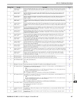
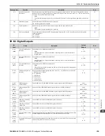
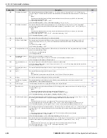
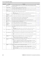
Setting Value
Function
Description
Ref.
3
Auxiliary Frequency
Reference 2
Sets Reference 3 through multi-step speed reference to enable the command reference (Auxiliary Frequency Reference
2) from the analog input terminal set here. This value is a percentage where the Maximum Output Frequency setting is
a setting value of 100%.
4
Output Voltage Bias
Set this parameter to input a bias signal and amplify the output voltage.
5
Accel/Decel Time Gain
Enters a signal to adjust the gain used for
C1-01 to C1-04 [Acceleration/Deceleration Times 1 and 2]
and
C1-09 [Fast
Stop Time]
when the full scale analog signal (10 V or 20 mA) is 100%.
6
DC Injection Braking
Current
Enters a signal to adjust the current level used for DC Injection Braking when the drive rated output current is 100%.
7
Torque Detection Level
Enters a signal to adjust the overtorque/undertorque detection level.
Note:
Use this function with
L6-01 [Torque Detection Selection 1]
. This parameter functions as an alternative to
L6-02
[Torque Detection Level 1]
.
8
Stall Prevent Level
During Run
Enters a signal to adjust the stall prevention level during run if the drive rated current is 100%.
9
Output Frequency Lower
Limit
Enters a signal to adjust the output frequency lower limit level as a percentage of the maximum output frequency.
B
PID Feedback
Enter the PID feedback value as a percentage of the maximum output frequency.
C
PID Setpoint
Enters the PID setpoint as a percentage of the maximum output frequency.
D
Frequency Bias
Enters the bias value added to the frequency reference as a percentage of the maximum output frequency.
E
Motor Temperature (PTC
Input)
Uses the motor Positive Temperature Coefficient (PTC) thermistor to prevent heat damage to the motor as a percentage
of the current value when the 10 V analog signal is input.
F
Not Used
Use this setting for unused terminals or to use terminals in through mode.
16
Differential PID
Feedback
Enters the PID differential feedback value if the full scale analog signal (10 V or 20 mA) is 100%.
1F
Not Used
Use this setting for unused terminals or to use terminals in through mode.
24
PID Feedback Backup
Enters the PID Feedback Backup signal for the drive to use when it loses the primary PID feedback set for
H3-xx = B
[PID Feedback]
.
Note:
The full-scale of the analog signal goes from
b5-71 [Min PID Transducer Scaling]
to
b5-38 [PID User Unit
Display Scaling]
.
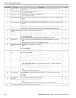
25
PI2 Control Setpoint
Enters the PI2 Control setpoint level as a percentage of the
S3-02 [PI2 Control Transducer Scale]
value.
Note:
Parameters
S3-03 [PI2 Control Decimal Place Pos]
and
S3-04 [PI2 Control Unit Selection]
set the resolution and
unit.
26
PI2 Control Feedback
Enters the PI2 Control feedback level as a percentage of the
S3-02 [PI2 Control Transducer Scale]
value.
Note:
Parameters
S3-03 [PI2 Control Decimal Place Pos]
and
S3-04 [PI2 Control Unit Selection]
set the resolution and
unit.
27
PI Auxiliary Control
Feedback
Enters the PI Auxiliary Control feedback value when
YF-01 = 1 [PI Aux Control Selection = Enabled]
.
Note:
•
The full-scale of the analog signal goes from 0% to
YF-02 [PI Aux Control Transducer Scale]
.
•
Parameter
YF-22 [PI Aux Level Decimal Place Pos]
sets the resolution.
2B
Emergency Override PID
Feedback
This input is the PID Feedback source when Emergency Override is running in PID mode (
S6-02 = 2 or 3 [Emergency
Override Ref Selection = System PID Mode or Independent PID Mode]
).
Note:
•
When
S6-02 = 2 [Emergency Override Ref Selection = System PID Mode]
, the full-scale of the analog signal
goes from
b5-71 [Min PID Transducer Scaling]
to
b5-38 [PID User Unit Display Scaling]
.
•
When
S6-02 = 3 [Independent PID Mode]
, the full-scale of the analog signal goes from
b5-71
to
S6-03 [EMOVR
Independent PID Scale]
.
•
When you set MEMOBUS register 3A93h bit 4, register 3A95h becomes the Emergency Override Feedback
source.
2C
Emergency Override PID
Setpoint
This input is the PID Setpoint source when Emergency Override is running in PID mode (
S6-02 = 2 or 3 [Emergency
Override Ref Selection = System PID Mode or Independent PID Mode]
).
Note:
•
When
S6-02 = 2 [Emergency Override Ref Selection = System PID Mode]
, the full-scale of the analog signal
goes from
b5-71 [Min PID Transducer Scaling]
to
b5-38 [PID User Unit Display Scaling]
.
•
When
S6-02 = 3 [Independent PID Mode]
, the full-scale of the analog signal goes from
b5-71
to
S6-03 [EMOVR
Independent PID Scale]
.
•
When you set MEMOBUS register 3A93h bit 5, register 3A96h becomes the Emergency Override Setpoint
source.
Содержание H6B1A002
Страница 2: ...This Page Intentionally Blank 2 YASKAWA SIEPYAIH6B01A HV600 AC Drive Bypass Technical Reference...
Страница 12: ...12 YASKAWA SIEPYAIH6B01A HV600 AC Drive Bypass Technical Reference...
Страница 30: ...1 2 Catalog Code and Nameplate Check 30 YASKAWA SIEPYAIH6B01A HV600 AC Drive Bypass Technical Reference...
Страница 68: ...2 9 Knock Out Hole Dimensions 68 YASKAWA SIEPYAIH6B01A HV600 AC Drive Bypass Technical Reference...
Страница 74: ...Page Intentionally Blank...
Страница 76: ...Page Intentionally Blank...
Страница 454: ...5 14 Z Bypass Parameters 454 YASKAWA SIEPYAIH6B01A HV600 AC Drive Bypass Technical Reference...
Страница 590: ...8 6 Storage Guidelines 590 YASKAWA SIEPYAIH6B01A HV600 AC Drive Bypass Technical Reference...
Страница 694: ...9 19 Defaults by Bypass and Drive Model 694 YASKAWA SIEPYAIH6B01A HV600 AC Drive Bypass Technical Reference...
Страница 768: ...10 6 MEMOBUS Modbus Communications 768 YASKAWA SIEPYAIH6B01A HV600 AC Drive Bypass Technical Reference...
Страница 780: ...11 3 European Standards 780 YASKAWA SIEPYAIH6B01A HV600 AC Drive Bypass Technical Reference...


