624
YASKAWA
SIEPYAIH6B01A HV600 AC Drive Bypass Technical Reference
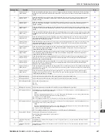
Setting Value
Function
Description
Ref.
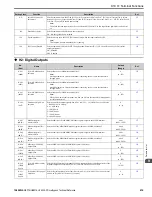
104
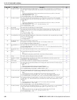
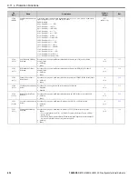
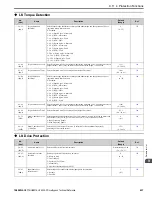
!Frequency Detection 1
The terminal activates when the output frequency >
“
L4-01 [Speed Agree Detection Level] + L4-02 [Speed Agree
Detection Width]
”
. After the terminal activates, the terminal stays activated until the output frequency is at the value of
L4-01
.
Note:
The detection function operates in the two motor rotation directions. The drive uses the
L4-01
value as the
forward/reverse detection level.
ON : The output frequency >
“
L4-01
+
L4-02
”
.
OFF : The output frequency <
L4-01
, or the output frequency ≤
“
L4-01
+
L4-02
”
105
!Frequency Detection 2
The terminal deactivates when the output frequency >
L4-01 [Speed Agree Detection Level]
. After the terminal
deactivates, the terminal stays deactivated until the output frequency is at the value of
“
L4-01
-
L4-02 [Speed Agree
Detection Width]
”
.
Note:
The detection function operates in the two motor rotation directions. The drive uses the
L4-01
value as the
forward/reverse detection level.
ON : The output frequency <
“
L4-01
-
L4-02
”
, or the output frequency ≤
L4-01
OFF : The output frequency >
L4-01
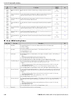
106
!Drive Ready
The terminal deactivates when the drive is ready and running.
107
!DC Bus Undervoltage
The terminal deactivates when the DC bus voltage or control circuit power supply is at the voltage set in
L2-05
[Undervoltage Detection Lvl (Uv1)]
or less. The terminal also deactivates when there is a fault with the DC bus
voltage.
ON : The DC bus voltage >
L2-05
OFF : The DC bus voltage ≤
L2-05
108
!During Baseblock (N.O.) The terminal deactivates during baseblock. When the drive is in baseblock, the drive output transistor stops switching
and does not make DC bus voltage.
ON : The drive is not in baseblock.
OFF : During baseblock.
109
!Frequency Reference
from Keypad
Shows the selected frequency reference source.
ON : Parameter
b1-01 [Frequency Reference Selection 1]
is the frequency reference source.
OFF : The keypad is the frequency reference source.
10B
!Torque Detection 1 (N.
O.)
The terminal deactivates when the drive detects overtorque or undertorque.
OFF : The output current/torque >
L6-02 [Torque Detection Level 1]
, or <
L6-02
for longer than the time set with
L6-
03 [Torque Detection Time 1]
.
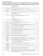
10C
!Frequency Reference
Loss
The terminal deactivates when the drive detects a loss of frequency reference.
10E
!Fault
The terminal deactivates when the drive detects a fault.
Note:
The terminal will not deactivate for
CPF00
and
CPF01 [Control Circuit Error]
faults.
110
!Alarm
The terminal deactivates when the drive detects a minor fault.
111
!Fault Reset Command
Active
The terminal deactivates when the drive receives the Reset command from the control circuit terminal, serial
communications, or the communication option.
112
!Timer Output
Use this setting when the drive uses the timer function as an output terminal.
113
!Speed Agree 2
The terminal deactivates when the output frequency is in the range of the frequency reference ±
L4-04 [Speed Agree
Detection Width (+/-)]
.
Note:
The detection function operates in the two motor rotation directions.
ON : The output frequency is not in the range of
“
frequency reference ±
L4-04
”
.
OFF : The output frequency is in the range of
“
frequency reference ±
L4-04
”
.
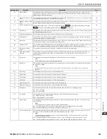
114
!User-Set Speed Agree 2
The terminal deactivates when the output frequency is in the range of
L4-03 [Speed Agree Detection Level (+/-)]
±
L4-
04 [Speed Agree Detection Width (+/-)]
and in the range of the frequency reference ±
L4-04
.
Note:
The detection level set in
L4-03
is a signed value. The drive will only detect in one direction.
ON : The output frequency is not in the range of
“
L4-03
±
L4-04
”
or the range of frequency reference ±
L4-04
.
OFF : The output frequency is in the range of
“
L4-03
±
L4-04
”
and the range of frequency reference ±
L4-04
.
115
!Frequency Detection 3
The terminal activates when the output frequency >
“
L4-03 [Speed Agree Detection Level (+/-)]
+
L4-04 [Speed Agree
Detection Width (+/-)]
”
. After the terminal activates, the terminal stays activated until the output frequency is at the
value of
L4-03
.
Note:
The detection level set in
L4-03
is a signed value. The drive will only detect in one direction.
ON : The output frequency >
“
L4-03
+
L4-04
”
OFF : The output frequency <
L4-03
, or the output frequency ≤
“
L4-03
+
L4-04
”
116
!Frequency Detection 4
The terminal deactivates when the output frequency >
L4-03 [Speed Agree Detection Level (+/-)]
. After the terminal
deactivates, the terminal stays deactivated until the output frequency is at the value of
“
L4-03
-
L4-04
”
.
Note:
The detection level set in
L4-03
is a signed value. The drive will only detect in one direction.
ON : The output frequency <
“
L4-03
-
L4-04
”
, or the output frequency ≤
L4-03
OFF : The output frequency >
L4-03
Содержание H6B1A002
Страница 2: ...This Page Intentionally Blank 2 YASKAWA SIEPYAIH6B01A HV600 AC Drive Bypass Technical Reference...
Страница 12: ...12 YASKAWA SIEPYAIH6B01A HV600 AC Drive Bypass Technical Reference...
Страница 30: ...1 2 Catalog Code and Nameplate Check 30 YASKAWA SIEPYAIH6B01A HV600 AC Drive Bypass Technical Reference...
Страница 68: ...2 9 Knock Out Hole Dimensions 68 YASKAWA SIEPYAIH6B01A HV600 AC Drive Bypass Technical Reference...
Страница 74: ...Page Intentionally Blank...
Страница 76: ...Page Intentionally Blank...
Страница 454: ...5 14 Z Bypass Parameters 454 YASKAWA SIEPYAIH6B01A HV600 AC Drive Bypass Technical Reference...
Страница 590: ...8 6 Storage Guidelines 590 YASKAWA SIEPYAIH6B01A HV600 AC Drive Bypass Technical Reference...
Страница 694: ...9 19 Defaults by Bypass and Drive Model 694 YASKAWA SIEPYAIH6B01A HV600 AC Drive Bypass Technical Reference...
Страница 768: ...10 6 MEMOBUS Modbus Communications 768 YASKAWA SIEPYAIH6B01A HV600 AC Drive Bypass Technical Reference...
Страница 780: ...11 3 European Standards 780 YASKAWA SIEPYAIH6B01A HV600 AC Drive Bypass Technical Reference...

