10.4 APOGEE FLN (P1) Communications
720
YASKAWA
SIEPYAIH6B01A HV600 AC Drive Bypass Technical Reference
the bypass. The setpoint for the control variable (water temperature set point) is unbundled and commanded by the
field panel, based on the building control strategy implemented in PPCL.
When this strategy is used, the point to unbundle and command for the set point is INPUT REF 1 (Point 60). The
control variable (for example, water temperature) can be monitored by unbundling PI FEEDBACK (Point 62). These
points are provided in units of percent, where 0% and 100% correspond to the range of the sensor being used to
measure the control variable. These points have default units in Hz. If other units are required, unbundle these points
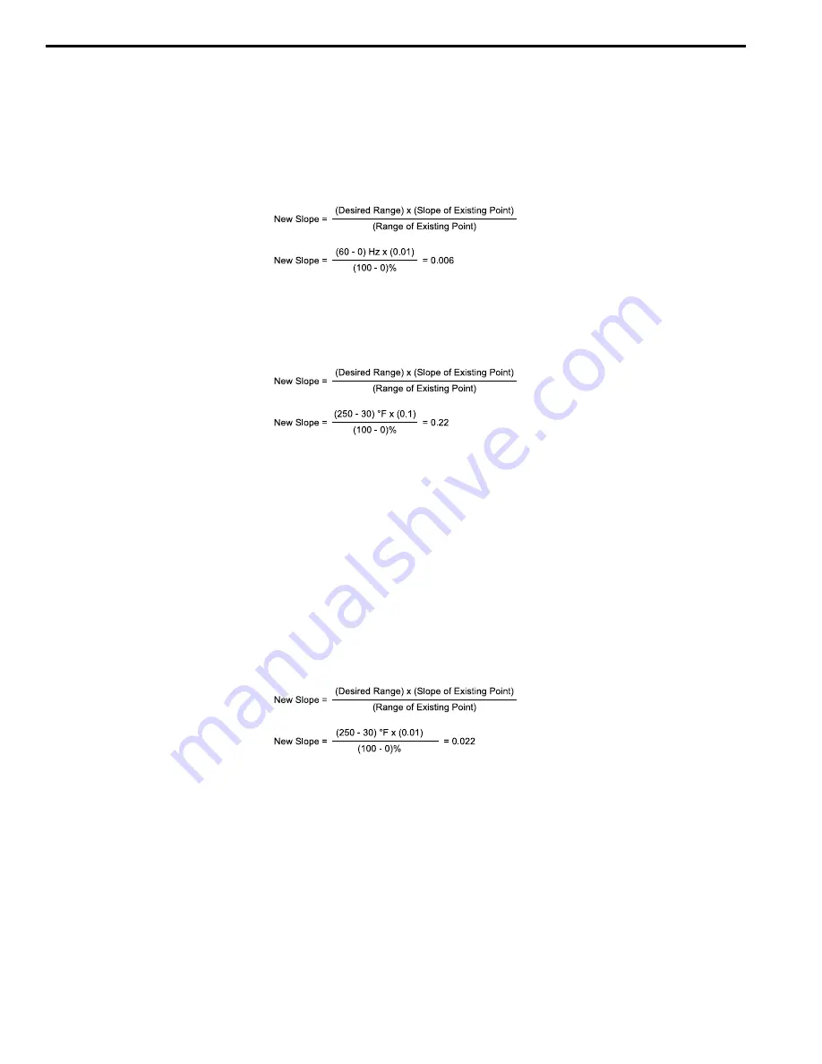
with appropriate slopes and intercepts. The new intercept will be equal to the lowest value of the desired range.
The following formulas allow the user to define a new slope and intercept to convert the unit.
Conversion Example
The bypass is controlling a fan, which in turn is controlling the water temperature from a cooling tower. The
temperature sensor has a range of -1 °C to +121 °C (30 °F to 250 °F). To unbundle the set point (INPUT REF 1), for
commanding in degrees Fahrenheit, where 0 to 60 Hz is equal to -1 °C to +121 °C: New Intercept = 30 (the
temperature that corresponds to 0%)
Note:
1. Desired Range = Range Maximum - Range Minimum
2. Range of Existing Point = Existing Range Maximum - Existing Range Minimum
■
Field Panel Controlled Feedback
In this strategy, the sensor is connected to the APOGEE FLN network at a remote location, and the control loop is
executed in PPCL. The drive speed command is passed from the field panel to the drive by commanding INPUT REF
1 (Point 60).
NOTICE:
Damage to Equipment. Yaskawa does not recommend a field panel controlled feedback strategy because it closes the
loop over the network. If you use field panel controlled feedback, it will cause a delay in processor scan time and network traffic. It
can cause a decrease or loss of control and cause damage to HVAC equipment.
Unbundle the Feedback
To unbundle the feedback (PI FEEDBACK) for monitoring in degrees Fahrenheit:
New Intercept = 30
Note:
1. Desired Range = Range Maximum - Range Minimum
2. Range of Existing Point = Existing Range Maximum - Existing Range Minimum
■
Other Functionalities
Enable these functions during start-up:
•
Enable the Bypass to Run
RUN ENABLE (Point 35) will operate only when
Z3-16 = 1 [Apogee Run Enable LD035 =Enable]
. If
Z3-16 = 0
,
Point 35 will have no effect.
•
Start and Stop the Bypass
CMD RUN.STOP (Point 24) can be commanded to run the bypass in the forward direction. STOP.RUN (Point 23)
shows the current status of the bypass.
•
Change Directions
Содержание H6B1A002
Страница 2: ...This Page Intentionally Blank 2 YASKAWA SIEPYAIH6B01A HV600 AC Drive Bypass Technical Reference...
Страница 12: ...12 YASKAWA SIEPYAIH6B01A HV600 AC Drive Bypass Technical Reference...
Страница 30: ...1 2 Catalog Code and Nameplate Check 30 YASKAWA SIEPYAIH6B01A HV600 AC Drive Bypass Technical Reference...
Страница 68: ...2 9 Knock Out Hole Dimensions 68 YASKAWA SIEPYAIH6B01A HV600 AC Drive Bypass Technical Reference...
Страница 74: ...Page Intentionally Blank...
Страница 76: ...Page Intentionally Blank...
Страница 454: ...5 14 Z Bypass Parameters 454 YASKAWA SIEPYAIH6B01A HV600 AC Drive Bypass Technical Reference...
Страница 590: ...8 6 Storage Guidelines 590 YASKAWA SIEPYAIH6B01A HV600 AC Drive Bypass Technical Reference...
Страница 694: ...9 19 Defaults by Bypass and Drive Model 694 YASKAWA SIEPYAIH6B01A HV600 AC Drive Bypass Technical Reference...
Страница 768: ...10 6 MEMOBUS Modbus Communications 768 YASKAWA SIEPYAIH6B01A HV600 AC Drive Bypass Technical Reference...
Страница 780: ...11 3 European Standards 780 YASKAWA SIEPYAIH6B01A HV600 AC Drive Bypass Technical Reference...


