UNREGISTERED VI
2*54 Engine, clutch and transmission
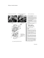
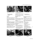
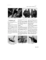
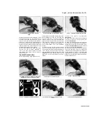
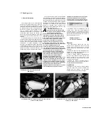
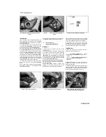
30.7d Fit a new O-ring onto the plug .
30.7e ... and press it into place
30.9 Fit the half-ring retainer into the slot
8
Install the selector forks (see Section 32).
9 Install the bearing half-ring retainer for the
right-hand end of the output shaft into its slot in
the upper crankcase half
(see illustration).
10
If it has not been removed, slide the output
shaft oil seal off the left-hand end of the shaft
(see illustration 25.11);
the seal must be
renewed. Lubricate the shaft and new seal with
clean oil and slide it onto the shaft. Smear the
seal rim with oil.
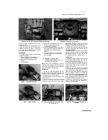
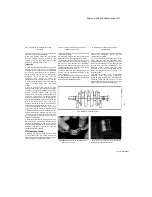
11 Lower the output shaft into position in the
crankcase half
(see illustration 30.2),
making
sure the selector fork guide pins are engaged
with their selector drum groove and the forks
themselves fit into the grooves in the pinions, and
the slot in the right-hand bearing engages
correctly with the bearing half-ring retainer, the
circlip on the left-hand bearing fits into its slot,
and the bearing locating pins fit into the cutouts
in the crankcase
(see illustration).
12 Make sure both transmission shafts are
correctly seated and their related pinions are
correctly engaged.
Caution: If the bearing half-ring retainer, circlip
and locating pins are not correctly engaged, the
crankcase halves will not seat correctly.
13 Position the gears in the neutral position and
check the shafts are free to rotate easily and
independently {ie the input shaft can turn whilst
the output shaft is held stationary) before
proceeding further.
14 Reassemble the crankcase halves (see
Section 25).
31 Transmission shafts
-
disassembly, inspection and
reassembly
1 Remove the transmission shafts from
the casing (see Section 30). Always disassemble
the transmission shafts separately to avoid
mixing up the components.
Input shaft disassembly
ffffJOftH
When disassembling the
UUHISI
transmission shafts, place
HllUT
the parts on
a long rod or
thread a wire through them to keep
them in order and facing the proper direction.
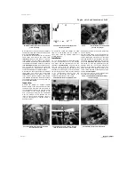
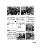
2 Remove the 2nd gear pinion from the left-hand
end of the shaft using a puller, referring to
Tools
and Workshop Tips
(Section 5) in the Reference
Section if required
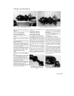
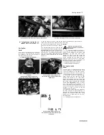
(see illustration).
If a legged
puller is being used, it will be easier to set it up
with the legs behind the 5th gear pinion, and
draw the 2nd and 5th pinions off together.
Note:
In our experience an hydraulic press was needed
to remove the 2nd gear pinion as it was so tight
on the shaft. Take the shaft to a properly
equipped workshop if necessary.
3 Slide the 5th gear pinion off the shaft
(see
illustration
31.1
7d).
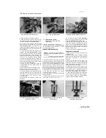
4 To remove the 5th gear pinion bush, set up a
puller behind the 3rd gear pinion and use
that to draw the bush off
(see illustration).
Remove the thrust washer and the 3rd gear
pinion
(see illustration 31.17a and 31.16).
5 Remove the circlip securing the 4th gear
pinion, then slide the splined washer and the
pinion off the shaft
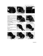
(see illustrations 31.15c, b
and
a). The 4th gear pinion bush is a press fit.
Do not remove it unless it needs to be renewed.
Remove it using a puller.
6 The 1st gear pinion is integral with the shaft.
Input shaft inspection
7
Wash all of the components in clean solvent
and dry them off.
8 Check the gear teeth for cracking, chipping,
pitting and other obvious wear or damage. Any
pinion that is damaged as such must be
renewed.
9 Inspect the dogs and the dog holes in the
gears for cracks, chips, and excessive wear
especially in the form of rounded edges. Make
sure mating gears engage properly. Renew the
paired gears as a set if necessary.
10 Check for signs of scoring or bluing on the
pinions, bushes and shaft. This could be caused
by overheating due to inadequate lubrication.
Check that all the oil holes and passages are
clear. Renew any damaged pinions or bushes.
11 Check that each mobile pinion moves freely
on the shaft or bush but without undue freeplay.
12 The shaft is unlikely to sustain damage
unless the engine has seized, placing an
30.11 Make sure that each pin (arrowed)
locates in its cutout
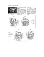
31.2 Use a puller or press to remove the
2nd gear pinion
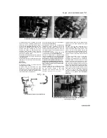
31.4 Draw off the bush using a puller
behind the 3rd gear pinion
Scaned by Stalker
UNREGISTERED VERSION OF PICTURE-DESK
Содержание XTZ750
Страница 174: ...UNREGISTERED VI ScanedbyStalker UNREGISTERED VI ...
Страница 207: ...Wiring diagrams 9 29 _____Scaned by Stalker 5 l 6o Cxj fi I JICM ...
Страница 208: ...UNREGISTERED VI 9 30 Wiring diagrams UNREGISTERED VERSION 01 ONREGISTEREDVI Scaned by Stalker ONREGISTERED VERSION 0 ...
Страница 209: ...I UNREGISTERED VI Wiring diagrams 9 31 ____ Scaned by Stalker UNREGISTERED VERSION OF PICTURE DESK ...
Страница 210: ...9 32 Wiring diagrams Scaned by Stalker ...
Страница 211: ...XTZ750 gauge Starter circuit Neutral Starter cut off relay switch rnotor ...

