2«26 Engine, clutch and transmission
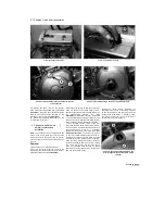
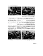
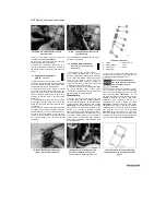
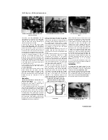
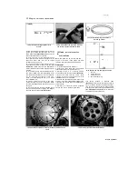
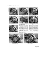
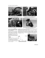
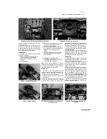
14.3a Prise out the circlip ...
14.3b ... then push out the pin and
remove the piston
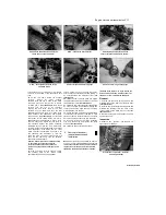
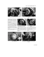
14.5 Removing the piston rings using <
ring removal and installation tool
flat-bladed screwdriver inserted into the notch
(see illustration).
Push the piston pin out from
the other side to free the piston from the
connecting rod
(see illustration).
If required,
remove the other circlip. Discard the removed
circlip(s) as new ones must be used. When the
piston has been removed, install its pin back into
its bore so that related parts do not get mixed up.
(IJjflJjfggj
To prevent the circlip from
UUIMB1
pingjng
aW
ay, pass a rod or
HlMT
screwdriver,
whose diameter
is greater than the gap between
the circlip ends, through the piston pin. This
will trap the circlip if it springs out.
JJffiJfl^l
If
a
piston pin is a tight fit in
l
~~
yaa
the piston
bosses,
soak a
HiMT
rag in boiling water then
,
wnn
g ^
out
ancl
wrgp
n
around the piston
-
this will expand the alloy
piston sufficiently to release its grip on the
pin. If the piston pin is particularly stubborn,
extract it using a drawbolt tool, but be
careful to protect the piston's working
surfaces.
Inspection
4 Before the inspection process can
be
carried
out, the pistons must be cleaned and the old
piston rings removed. Note that if the cylinders
are being rebored, piston inspection can be
overlooked as new ones will be fitted.
5 Using your thumbs or a piston ring removal
and installation tool, carefully remove the rings
from the pistons
(see illustration).
Do not nick or
gouge the pistons in the process. Carefully note
which way up each ring fits and in which groove
as they must be installed in their original
positions if being re-used. The upper surface of
each ring has a manufacturer's mark or letter at
one end.
6 Scrape all traces of carbon from the tops of
the pistons. A hand-held wire brush or a piece of
fine emery cloth can be used once most of
the deposits have been scraped away. Do not,
under any circumstances, use a wire brush
mounted in a drill motor to remove deposits from
the pistons; the piston material is soft and will be
eroded away by the wire brush.
7 Use a piston ring groove cleaning tool to
remove any carbon deposits from the ring
grooves. If a tool is not available, a piece broken
off an old ring will do the job. Be very careful to
remove only the carbon deposits. Do not remove
any metal and do not nick or gouge the sides of
the ring grooves.
8 Once the deposits have been removed, clean
the pistons with solvent and dry them thoroughly.
If the identification previously marked on the
piston is cleaned off, be sure to re-mark it with
the correct identity. Make sure the oil return
holes below the oil ring groove are clear.
9 Carefully inspect each piston for cracks
around the skirt, at the pin bosses and at the ring
lands. Normal piston wear appears as even,
vertical wear on the thrust surfaces of the piston
and slight looseness of the top ring in its groove.
If the skirt is scored or scuffed, the engine may
have been suffering from overheating and/or
abnormal combustion, which caused excessively
high operating temperatures. The oil pump
should be checked thoroughly. Also check that
the circlip grooves are not damaged.
10 A hole in the piston crown, an extreme to
be sure, is an indication that abnormal
combustion (pre-ignition) was occurring. Burned
areas at the edge of the piston crown are usually
evidence of spark knock (detonation). If any of
the above problems exist, the causes must be
corrected or the damage will occur again.
11
Measure the piston ring-to-groove clearance
by laying each piston ring in its groove and
slipping a feeler gauge in beside it
(see
illustration).
Make sure you have the correct ring
for the groove (see Step 5). Check the clearance
at three or four locations around the groove. If the
clearance is greater than specified, renew both
the piston and rings as a set. If new rings are
being used, measure the clearance using the
new rings. If the clearance is greater than that
specified, the piston is worn and must be
renewed.
12 Check the piston-to-bore clearance by
measuring the bore (see Section 13) and the
piston diameter. Make sure each piston is
matched to its correct cylinder. Measure the
piston 4.5 mm (1991 to 1995 TDM models), 4.7
mm (XTZ models), or 5.5 mm (1996-on TDM and
all TRX models) up from the bottom of the skirt
and at 90° to the piston pin axis
(see
illustration).
Subtract the piston diameter from
the bore diameter to obtain the clearance. If it is
greater than the specified figure, the piston must
be renewed (assuming the bore itself is within
limits, otherwise a rebore is necessary).
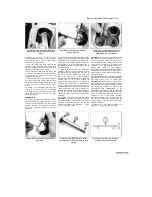
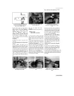
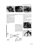
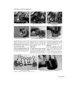
toned by Stalker
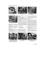
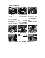
14.11 Measure the piston ring-to-groove
clearance with a feeler gauge
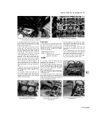
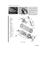
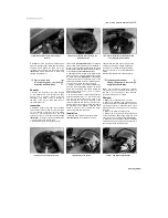
14.12 Measure the piston diameter with a
micrometer at the specified distance from
the bottom of the skirt
Содержание XTZ750
Страница 174: ...UNREGISTERED VI ScanedbyStalker UNREGISTERED VI ...
Страница 207: ...Wiring diagrams 9 29 _____Scaned by Stalker 5 l 6o Cxj fi I JICM ...
Страница 208: ...UNREGISTERED VI 9 30 Wiring diagrams UNREGISTERED VERSION 01 ONREGISTEREDVI Scaned by Stalker ONREGISTERED VERSION 0 ...
Страница 209: ...I UNREGISTERED VI Wiring diagrams 9 31 ____ Scaned by Stalker UNREGISTERED VERSION OF PICTURE DESK ...
Страница 210: ...9 32 Wiring diagrams Scaned by Stalker ...
Страница 211: ...XTZ750 gauge Starter circuit Neutral Starter cut off relay switch rnotor ...

