Every 16,000 miles (24,000 km) or 2 years
1.25
7
Fill the cooling system with clean water mixed
with a flushing compound. Make sure the flushing
compound
is
compatible
with
aluminium
components, and follow the manufacturer's
instructions carefully.
8 Start the engine and allow it to reach normal
operating temperature. Let it run for about ten
minutes.
9 Stop the engine. Let it cool for a while, then
cover the pressure cap with a heavy rag and turn
it anti-clockwise to the first stop, releasing any
pressure that may be present in the system.
Once the hissing stops, push down on the cap
and remove it completely.
10 Drain the system once again.
11 Fill the system with clean water and repeat
the procedure in Steps 7 to 9.
Refilling
12
Fit a new sealing washer to each drain plug
and tighten them to the torque setting specified
at the beginning of the Chapter.
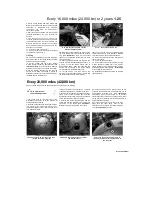
13 Fill the system with the proper coolant
mixture (see this Chapter's Specifications)
(see
illustration). Note:
Pour the coolant in slowly to
minimise the amount of air entering the system.
When the radiator appears full, pull the bike
upright off its stand and shake it slightly to
dissipate the coolant, then place the bike back on
the stand and top the radiator up.
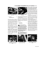
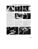
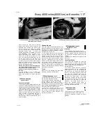
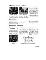
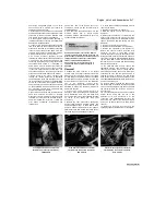
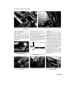
27.13 Use only the specified coolant
mixture to fill the system
...
14
When the system is full (all the way up to the
top of the radiator filler neck), install the pressure
cap
(see illustration).
Now fill the coolant
reservoir to the UPPER level mark (see
Daily
(pre-ride) checks).
15 Start the engine and allow it to idle for 2 to 3
minutes. Flick the throttle twistgrip part open 3 or
4 times, so that the engine speed rises to
approximately 4000 - 5000 rpm, then stop the
engine. Any air trapped in the system should
have bled back to the radiator filler neck.
16 Let the engine cool then remove the
pressure cap as described in Step 1. Check that
the coolant level is still up to the radiator
27.14 ... then fit the pressure cap
filler neck. If it's low, add the specified mixture
until it reaches the top of the filler neck. Refit the
cap, then on TRX models fit the security bolt.
17 Check the coolant level in the reservoir and
top up if necessary.
18 Check the system for leaks.
19 Do not dispose of the old coolant by pouring
it down the drain. Instead pour it into a heavy
plastic container, cap it tightly and take it into an
authorised disposal site or garage - see
Warning
at the beginning of this Section.
20 Install the seat and body panels as required
(see Chapter 8).
Every 28,000 miles (42,000 km)
Cany
out all the items under the 4000 mile (6000 km) check, plus the following
m
28 Valve clearances -
|^
check and adjustment
«
1 The engine must be completely cool for this
maintenance procedure, so let the machine sit
overnight before beginning.
2 Remove the fuel tank and the air filter housing
(see Chapter 4), the radiator (see Chapter 3), the
spark plugs (see Section 2), and the valve cover
(see Chapter 2). Each
cylinder is referred to by a number: no. 1 cylinder
is the left cylinder and no. 2 cylinder is the right.
3 Make a chart or sketch of all valve positions so
that a note of each clearance can be made
against the relevant valve. There are two exhaust
valves and three inlet valves per cylinder.
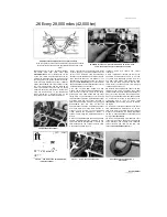
4 Unscrew the timing inspection plug and the
centre plug from the alternator cover on the left-
hand side of the engine
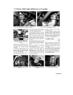
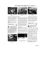
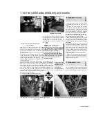
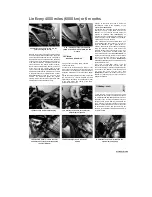
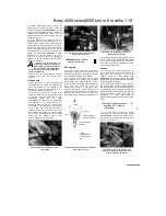
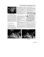
(see illustration).
Discard the plug O-rings as new ones should
be used. The engine can be turned using a 19 mm
socket on the alternator rotor bolt and turning it in an
anti-clockwise direction only
(see illustration).
Alternatively, place the motorcycle on an auxiliary
stand so that the ^ rear wheel is off the ground, select
a high gear and rotate the rear wheel by hand in its
normal direction of rotation.
5 Turn the engine until the 'I' mark on the rotor
aligns with the static timing mark on the
alternator cover (a notch in the timing inspection
hole)
(see illustration),
and the
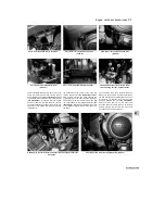
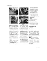
28.4a Unscrew the timing inspection plug
(A) and the centre plug (B)
28.4b Turn the engine using a socket on
the alternator bolt
28.5a Turn the engine until the mark on
the rotor (A) aligns with the static mark on
the cover (B)
Scaned by Stalker
Содержание XTZ750
Страница 174: ...UNREGISTERED VI ScanedbyStalker UNREGISTERED VI ...
Страница 207: ...Wiring diagrams 9 29 _____Scaned by Stalker 5 l 6o Cxj fi I JICM ...
Страница 208: ...UNREGISTERED VI 9 30 Wiring diagrams UNREGISTERED VERSION 01 ONREGISTEREDVI Scaned by Stalker ONREGISTERED VERSION 0 ...
Страница 209: ...I UNREGISTERED VI Wiring diagrams 9 31 ____ Scaned by Stalker UNREGISTERED VERSION OF PICTURE DESK ...
Страница 210: ...9 32 Wiring diagrams Scaned by Stalker ...
Страница 211: ...XTZ750 gauge Starter circuit Neutral Starter cut off relay switch rnotor ...

