9*22 Electrical system
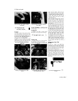
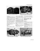
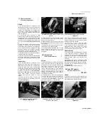
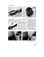
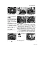
29.6 Withdraw the armature
29.7 Unscrew the terminal nut (A) and remove the washers, then
lift out the brushplate (B)
6
Withdraw the armature from the main
housing
(see illustration).
7
Noting the correct fitted location of each
component, unscrew the terminal nut and
remove it along with its washer and the
insulating washers
(see illustration).
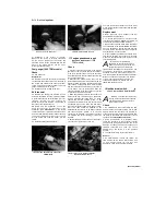
Withdraw the brushplate assembly and
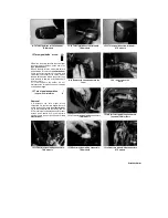
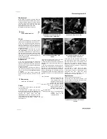
29.8 Measure the length of each brush
terminal bolt from the main housing. Remove
the brushplate seat
(see illustration 29.15a).
Inspection
8
The parts of the starter motor that are most
likely to require attention are the brushes.
Measure the length of the brushes and
compare the results to the brush length listed
in this Chapter's Specifications
(see
illustration).
If any of the brushes are worn
beyond the service limit, renew the brush
assembly. If the brushes are not worn
excessively, nor cracked, chipped, or
otherwise damaged, they may be re-used.
9 Inspect the commutator bars on the
armature for scoring, scratches and
discoloration. The commutator can be
cleaned and polished with crocus cloth, but
do not use sandpaper or emery paper. After
cleaning, wipe away any residue with a cloth
soaked in electrical system cleaner or
denatured alcohol. Measure the diameter of
the commutator and compare It to the
specifications. If it has worn below the wear
limit, renew the starter motor. Measure the
depth of the insulating Mica below the surface
of the commutator bars. If the Mica is less
than the depth specified, scrape it away until
the specified depth is reached.
10
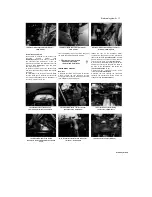
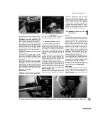
Using an ohmmeter or a continuity test
light, check for continuity between the
commutator bars
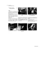
(see illustration).
Continuity
should exist between each bar and all of the
others. Also, check for continuity between the
commutator bars and the armature shaft
(see
illustration).
There should be no continuity
(infinite resistance) between the commutator
and the shaft. If the checks indicate
otherwise, the armature is defective.
11 Check for continuity between the terminal
bolt and the housing (when assembled). There
should be no continuity (infinite resistance).
12
Check the front end of the armature shaft
for worn, cracked, chipped and broken teeth.
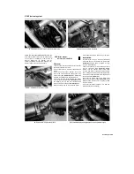
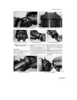
29.10a Continuity should exist between the commutator bars
29.10b There should be no continuity between the commutator
bars and the armature shaft
Scaned by Stalker
UNREGISTERED VERSION OF PICTURE-DESK
Содержание XTZ750
Страница 174: ...UNREGISTERED VI ScanedbyStalker UNREGISTERED VI ...
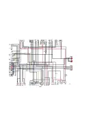
Страница 207: ...Wiring diagrams 9 29 _____Scaned by Stalker 5 l 6o Cxj fi I JICM ...
Страница 208: ...UNREGISTERED VI 9 30 Wiring diagrams UNREGISTERED VERSION 01 ONREGISTEREDVI Scaned by Stalker ONREGISTERED VERSION 0 ...
Страница 209: ...I UNREGISTERED VI Wiring diagrams 9 31 ____ Scaned by Stalker UNREGISTERED VERSION OF PICTURE DESK ...
Страница 210: ...9 32 Wiring diagrams Scaned by Stalker ...
Страница 211: ...XTZ750 gauge Starter circuit Neutral Starter cut off relay switch rnotor ...

