Non-scheduled maintenance 1.29
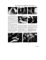
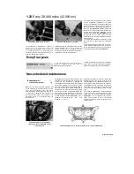
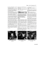
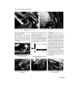
30.4 Vertical adjuster (A), horizontal
adjuster (B) - TRX models
corner of each headlight unit. For the left-hand
beam, turn it clockwise to move the beam to the
left, and anti-clockwise to move it to the right. For
the right-hand beam, turn it clockwise to move
the beam to the right, and anti-clockwise to move
it to the left. 4 On TRX models, vertical
adjustment is made by turning the adjuster screw
on the bottom left corner of the headlight unit
(see illustration).
Turn it clockwise to raise the
beam, and anti -clockwise to lower it. Horizontal
adjustment is made by turning the adjuster screw
on the top right corner of the headlight unit. Turn
it clockwise to move the beam to the left, and
anti-clockwise to move it to the right.
31 Cylinder compression -
check
1 Among other things, poor engine
performance may be caused by leaking
valves, incorrect valve clearances, a
leaking head gasket, or worn pistons,
rings
and/or
cylinder
walls.
A
cylinder
compression check will help pinpoint these
conditions and can also indicate the presence of
excessive carbon deposits in the cylinder heads.
2 The only tools required are a compression
gauge and a spark plug wrench. A compression
gauge with a threaded end for the spark plug 12
mm diameter hole is preferable to the type which
requires hand pressure to maintain a tight seal.
Depending on the outcome of the initial test, a
squirt-type oil can may also be needed.
3 Make sure the valve clearances are correctly
set (see Section 28) and that the cylinder head
fasteners are tightened to the correct torque
setting (see Chapter 2).
4 Refer to
Fault Finding Equipment
in the
Reference section for details of the compression
test. Refer to the specifications at the beginning
of the Chapter for compression figures.
32 Engine - oil pressure check
1 None of the models covered in this
manual are fitted with an oil pressure
warning light. If a lubrication problem is
suspected, first check
the oil level (see
Daily (pre-ride) checks)
2 If the oil level is correct, an oil pressure check
must be carried out.
3 To check the oil pressure, slacken the oil
gallery bolt in the left-hand side of the cylinder
head - there is no need to remove it
(see
illustration).
4
Start the engine and allow it to idle. After a
short while oil should begin to seep out from the
oil gallery plug
(see illustration).
If no oil has
appeared after one minute, stop the engine
immediately.
5 If the oil does not appear after one minute,
either the pressure regulator is stuck open, the
oil pump is faulty, the oil strainer or filter is
blocked, or there is other engine damage. Begin
diagnosis by checking the oil filter (Section 22 of
this Chapter), strainer and regulator, then the oil
pump (see Chapter 2). If those items check out
okay, chances are the
bearing oil clearances are excessive and the
engine needs to be overhauled.
6 If the oil appears very quickly and spurts out,
the pressure may be too high, meaning either an
oil passage is clogged, the regulator is stuck
closed or the wrong grade of oil is being used.
7 Refer to Chapter 2 and rectify any problems
before running the engine again.
8 Tighten the oil gallery bolt to the torque setting
specified at the beginning of the Chapter.
Warning: Petrol (gasoline) is
extremely flammable, so take extra
precautions when you work on any
part of the fuel system. Don't smoke
or allow open flames or bare light
bulbs near the work area, and don't work in a
garage where a natural gas-type appliance is
present. If you spill any fuel on your skin,
rinse it off immediately with soap and water.
When you perform any kind of work on the
fuel system, wear safety glasses and have a
fire extinguisher suitable for a Class B type
fire (flammable liquids) on hand.
1 The fuel delivery and vacuum hoses should be
renewed after a few years regardless of their
condition.
2 Remove the fuel tank (see Chapter 4).
Disconnect the fuel hoses from the fuel tap, fuel
pump and from the carburettors, noting the
routing of each hose and where it connects (see
Chapter 4 if required). It is advisable to make a
sketch of the various hoses before removing them
to ensure they are correctly installed.
3 Secure each new hose to its unions using new
clamps. Run the engine and check that there are
no fuel leaks before taking the machine out on the
road.
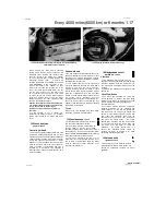
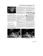
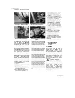
32.3 Slacken the gallery bolt (arrowed)...
32.4 ... then start the engine and check that the oil dribbles out
within a minute
Scaned by Stalker
t
^
^
A
Содержание XTZ750
Страница 174: ...UNREGISTERED VI ScanedbyStalker UNREGISTERED VI ...
Страница 207: ...Wiring diagrams 9 29 _____Scaned by Stalker 5 l 6o Cxj fi I JICM ...
Страница 208: ...UNREGISTERED VI 9 30 Wiring diagrams UNREGISTERED VERSION 01 ONREGISTEREDVI Scaned by Stalker ONREGISTERED VERSION 0 ...
Страница 209: ...I UNREGISTERED VI Wiring diagrams 9 31 ____ Scaned by Stalker UNREGISTERED VERSION OF PICTURE DESK ...
Страница 210: ...9 32 Wiring diagrams Scaned by Stalker ...
Страница 211: ...XTZ750 gauge Starter circuit Neutral Starter cut off relay switch rnotor ...

