2*12 Engine, clutch and transmission
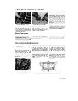
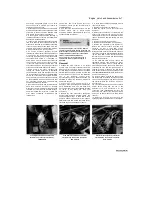
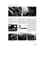
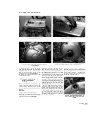
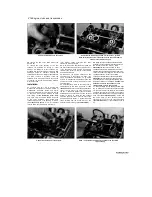
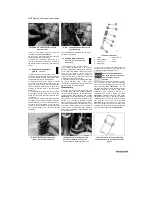
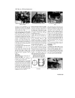
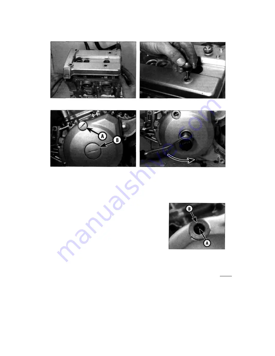
7.10a Install the valve cover...
7.10b ... and tighten the bolts
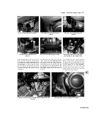
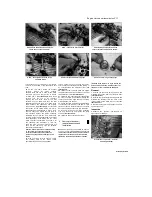
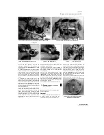
8.2a Unscrew the timing inspection plug (A) and the
centre plug (B)
8.2b Turn the engine using a socket on the alternator bolt
10
Position the valve cover on the cylinder
head, making sure the gaskets stay in place
(see
illustration).
Install the cover bolts and tighten
them to the torque setting specified at the
beginning of the Chapter
(see illustration).
11
Install the remaining components in the
reverse order of removal.
8 Camshafts and followers -
removal, inspection and
installation
Note:
The camshafts can be removed with the
engine in the frame. Place rags over the spark
plug holes and the camchain tunnel to prevent
any component from dropping into the engine on
removal.
Removal
1 Remove the valve cover (see Section 7).
2 Unscrew the timing inspection plug and the
centre plug from the alternator cover on the left-
hand side of the engine
(see illustration).
Discard the plug O-rings as new ones should be
used. The engine can be turned using a 19 mm
socket on the alternator rotor bolt and turning it in
an
anti-clockwise
direction
only
(see
illustration).
Alternatively, place the motorcycle
on an auxiliary stand so that the rear wheel is off
the ground, select a high gear and rotate the rear
wheel by hand in its normal direction of rotation.
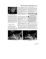
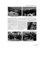
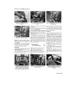
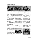
3 Turn the engine until the T mark on the rotor
aligns with the static timing mark on the alternator
cover (a notch in the timing inspection hole), and
the camshaft lobes for the No. 1 (left-hand)
cylinder are facing away from each other
(see
illustration). Note: Do
not confuse the T mark
on the rotor (which indicates TDC) with the 'H'
mark which will appear first and which indicates
the firing point of the ignition system.
If the cam
lobes are facing towards each other, rotate the
engine anti-clockwise 360° (one full turn) so that
the 'I' mark again aligns with the static timing
mark. The camshaft lobes will now be facing
away from each other and the No. 1 cylinder is at
TDC (top dead centre) on the
compression stroke. Before disturbing the
camshafts, make a note of the timing markings
on the sprockets and how they align with the
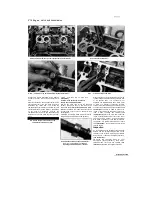
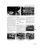
cylinder head. With the No. 1 cylinder at TDC,
The 'E' mark on the exhaust camshaft sprocket is
parallel with the cylinder head top
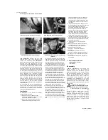
8.3a Turn the engine until the mark on the
rotor (A) aligns with the static mark on the
cover(B)
Scaned by Stalker
|
Содержание XTZ750
Страница 174: ...UNREGISTERED VI ScanedbyStalker UNREGISTERED VI ...
Страница 207: ...Wiring diagrams 9 29 _____Scaned by Stalker 5 l 6o Cxj fi I JICM ...
Страница 208: ...UNREGISTERED VI 9 30 Wiring diagrams UNREGISTERED VERSION 01 ONREGISTEREDVI Scaned by Stalker ONREGISTERED VERSION 0 ...
Страница 209: ...I UNREGISTERED VI Wiring diagrams 9 31 ____ Scaned by Stalker UNREGISTERED VERSION OF PICTURE DESK ...
Страница 210: ...9 32 Wiring diagrams Scaned by Stalker ...
Страница 211: ...XTZ750 gauge Starter circuit Neutral Starter cut off relay switch rnotor ...

