9»26 Electrical system
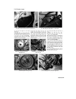
32.6c Unscrew the two bolts and remove the inner cover
32.7 Gearchange arm/shaft alignment - TRX models
top rear bolt, and remove the cover
(see
illustration).
7
On TRX models, unscrew the gearchange
lever linkage arm pinchbolt and remove the arm
from the shaft, noting the alignment of the punch
mark with the slit in the clamp
(see illustration).
If no mark is visible, make your own before
removing the arm so that it can be correctly
aligned with the shaft on installation.
32.8 Unscrew the bolts (arrowed) and
remove the cover
Unscrew the bolts securing the outer front
sprocket cover and remove the cover, then
unscrew the bolts securing the inner sprocket
cover, noting the clip secured by the top rear
bolt, and remove the cover. 8 Working in a criss-
cross pattern, unscrew the bolts securing the
alternator cover and remove the cover
(see
illustration).
Discard the gasket as a new one
must be used. Note
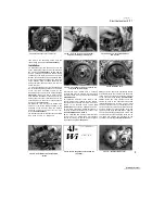
32.9 Withdraw the shaft (arrowed) and
remove the gear
the position of the dowels and remove them if
loose.
9 Withdraw
the
shaft
from
the
starter
idle/reduction gear and remove the gear,
noting how it fits
(see illustration).
10
To remove the rotor bolt it is necessary to
stop the rotor from turning. If a rotor holding
strap or tool is not available, and if the engine is
still in the fame, place the transmission in gear
and have an assistant apply the rear brake, then
unscrew the bolt
(see illustration).
11
To remove the rotor from the shaft it is
necessary to use
a
rotor puller. Yamaha provide
a special tool (Pt. Nos. 90890-01362 and 90890-
01382, or alternatively
a
similar tool can be set
up as shown, using the threaded holes in the
rotor
(see illustration).
After the rotor has been
removed, remove the Woodruff key from the slot
in the crankshaft for safekeeping if loose
(see
illustration 32.14a).
12
To remove the stator from the cover, remove
the three screws securing the stator, and the two
screws securing the pick-up coil,
32.10 Unscrew the rotor bolt (arrowed)
32.11 Drawing the rotor off the shaft using a puller
Staged by Stalker
Содержание XTZ750
Страница 174: ...UNREGISTERED VI ScanedbyStalker UNREGISTERED VI ...
Страница 207: ...Wiring diagrams 9 29 _____Scaned by Stalker 5 l 6o Cxj fi I JICM ...
Страница 208: ...UNREGISTERED VI 9 30 Wiring diagrams UNREGISTERED VERSION 01 ONREGISTEREDVI Scaned by Stalker ONREGISTERED VERSION 0 ...
Страница 209: ...I UNREGISTERED VI Wiring diagrams 9 31 ____ Scaned by Stalker UNREGISTERED VERSION OF PICTURE DESK ...
Страница 210: ...9 32 Wiring diagrams Scaned by Stalker ...
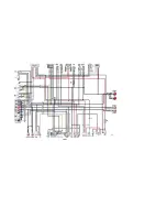
Страница 211: ...XTZ750 gauge Starter circuit Neutral Starter cut off relay switch rnotor ...

