Fuel
and
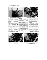
exhaust
systems 4*3
1 General Information and
precautions
General information
The fuel system consists of the fuel tank with
internal filter, fuel tap, fuel pump, carburettors, fuel
hoses and control cables.
On TDM models, a remote fuel tap is fitted for
normal operation, while the filter is integral with the
fuel outlet assembly from the tank. On TRX
models, a vacuum-operated fuel tap with integral
filter is mounted on the left-hand side of the fuel
tank. On XTZ models, a fuel tap with integral filter
is mounted on each side of the fuel tank.
Fuel is pumped to the carburettors by a
vacuum-operated fuel pump on all TRX and XTZ
models and 1991 to 1998 TDM models. The 1999
TDM model has an electrically-operated fuel
pump.
The carburettors used on all models are CV
types. There is a carburettor for each cylinder. For
cold starting, a choke knob is connected to the
carburettors by a cable. On 1991 to 1995 TDM
models, the choke knob is mounted above the
front sprocket cover; on 1996-on TDM models and
XTZ models it is mounted on the handlebars; on
TRX models it is mounted on the frame between
the fuel tank and the fairing. On 1996-on TDM and
TRX models the carburettors are warmed by the
engine's coolant.
Air is drawn into the carburettors via an air filter
which is housed under the fuel tank.
The exhaust system is a two-into-two design.
Many of the fuel system service procedures are
considered routine maintenance items and for that
reason are included in Chapter 1.
Precautions
Warning: Petrol (gasoline) is
any fuel on your skin, rinse it off immediately
with soap and water. When you perform any
kind of work on the fuel system, wear safety
glasses and have a fire extinguisher suitable
for a class B type fire (flammable liquids) on
hand.
Always perform service procedures in a well-
ventilated area to prevent a build-up of fumes.
Never work in a building containing a gas
appliance with a pilot light, or any other form of
naked flame. Ensure that there are no naked
light bulbs or any sources of flame or sparks
nearby.
Do not smoke (or allow anyone else to smoke)
while in the vicinity of petrol (gasoline) or of
components containing it. Remember the
possible presence of vapour from these sources
and move well clear before smoking.
Check all electrical equipment belonging to the
house, garage or workshop where work is being
undertaken (see the Safety first! section of this
manual). Remember that certain electrical
appliances such as drills, cutters etc. create
sparks in the normal course of operation and
must not be used near petrol (gasoline) or any
component containing it. Again, remember the
possible presence of fumes before using
electrical equipment.
Always mop up any spilt fuel and safety
dispose of the rag used.
Any stored fuel that is drained off during
servicing work must be kept in sealed containers
that are suitable for holding petrol (gasoline), and
clearly
marked
as
such;
the
containers
themselves should be kept in a safe place. Note
that this last point applies equally to the fuel tank
if it is removed from the machine; also remember
to keep its filler cap closed at all times.
Read the Safety first! section of this manual
carefully before starting work.
2 Fuel tank and fuel
tap(s) -
removal and installation
A
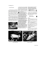
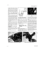
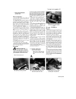
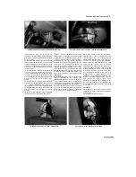
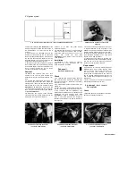
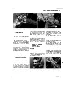
2.2 Detach the lower hose (A), then
unscrew the bolts (B) and displace
the tap
Fuel tank - TDM models
Removal
1 Make sure the fuel cap is secure and the fuel
tap is in the OFF position. On 1991 to 1995
models, remove the seat, the fairing side panels
and the fairing (see Chapter 8). On 1996-on
models, remove the seat, the fairing side panels
and the side trim panels (see Chapter 8).
2 On 1991 to 1995 models, release the clamp
securing the lower hose (to the fuel pump) on the
remote fuel tap and detach the hose, then
unscrew the bolts securing the tap and displace
it
(see illustration).
3
On 1996 to 1998 models, either proceed as
described for the earlier models in Step 2, or
close the tap on the fuel outlet assembly under
the tank and detach the fuel hoses from the
outlet, noting which fits where. Note that access
may be restricted until the tank bolts have been
removed and the tank can
be
raised at the rear.
4 On 1999 models, turn the fuel tap lever to the
OFF position. Release the clamp securing the
hose to the side of the fuel tap and detach the
hose.
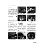
5 Unscrew the bolt securing the rear of the tank,
then unscrew the bolt on each side at the front
and release the trim panel from the lug
(see
illustrations).
Raise the tank at the rear and
release the clamp securing the breather hose to
its union and detach the hose
(see illustration).
On 1991 to 1998
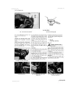
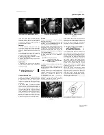
2.5a Unscrew the rear bolt (arrowed)...
2.5b ... and the bolt on each side (A), and
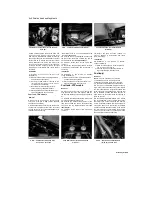
release the trim from the lug (B)
2.5c Detach the hose from the union
(arrowed) and remove the tank
Scaned by Stalker
extremely flammable, so take extra
precautions when you work on any part of
the fuel system. Don't smoke or allow open
flames or bare light bulbs near the work area,
and don't work in a garage where a natural
gas-type appliance is present. If you spill
A
Warning: Refer to the precautions
given in Section 1 before starting
work.
Содержание XTZ750
Страница 174: ...UNREGISTERED VI ScanedbyStalker UNREGISTERED VI ...
Страница 207: ...Wiring diagrams 9 29 _____Scaned by Stalker 5 l 6o Cxj fi I JICM ...
Страница 208: ...UNREGISTERED VI 9 30 Wiring diagrams UNREGISTERED VERSION 01 ONREGISTEREDVI Scaned by Stalker ONREGISTERED VERSION 0 ...
Страница 209: ...I UNREGISTERED VI Wiring diagrams 9 31 ____ Scaned by Stalker UNREGISTERED VERSION OF PICTURE DESK ...
Страница 210: ...9 32 Wiring diagrams Scaned by Stalker ...
Страница 211: ...XTZ750 gauge Starter circuit Neutral Starter cut off relay switch rnotor ...

