Every 4000 miles (6000 km) or 6 months 1.1.1
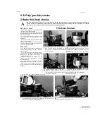
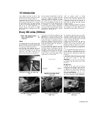
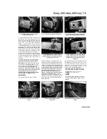
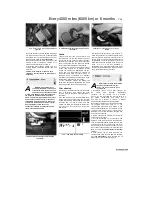
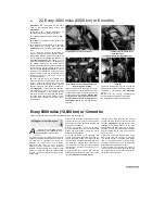
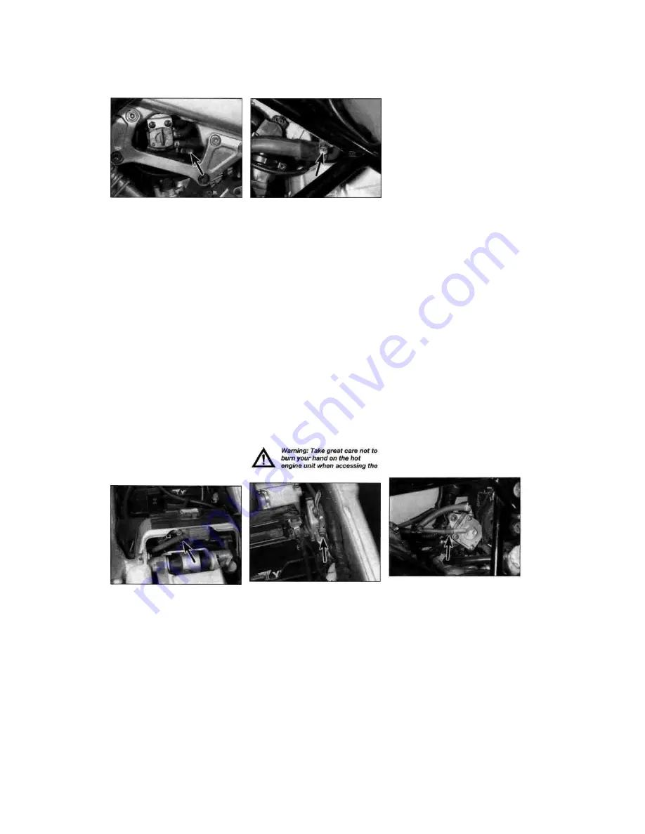
3.3a Idle speed adjuster screw (arrowed) -
TDM models
3 Idle speed -
§^
check and adjustment
1
The idle speed should be checked and
adjusted before and after the carburettors are
synchronised (balanced) and when it is obviously
too high or too low. Before adjusting the idle
speed, make sure the valve clearances and
spark plug gaps are correct. Also, turn the
handlebars back-and-forth and see if the idle
speed changes as this is done. If it does, the
throttle cable may not be adjusted or routed
correctly, or may be worn out. This is a
dangerous condition that can cause loss of
control of the bike. Be sure to correct this
problem before proceeding.
2 The engine should be at normal operating
temperature, which is usually reached after 10 to
15 minutes of stop-and-go riding. Make sure the
transmission is in neutral, and place the
motorcycle on its sidestand.
3 On TDM and TRX models, the idle speed
adjuster is located on the left-hand side
(see
illustrations).
On XTZ models, the adjuster is
located at the back of the carburettors between
the float chambers. With the engine idling, adjust
the idle speed by turning the adjuster screw until
the idle
speed listed
in
this
Chapter's
Specifications is obtained. Turn the screw
clockwise to increase idle speed, and anti-
clockwise to decrease it.
3.3b Idle speed adjuster screw (arrowed) -
TRX models
4
Snap the throttle open and shut a few times,
then recheck the idle speed. If necessary, repeat
the adjustment procedure.
5 If a smooth, steady idle can't be achieved, the
fuel/air mixture may be incorrect (check the pilot
screw settings - see Chapter 4) or the
carburettors may need synchronising (see
Section 4). Also check the inlet manifold rubbers
for cracks which will cause an air leak, resulting in
a weak mixture.
4 Carburettors -
^
synchronisation
^
Warning: Petrol (gasoline) is
extremely flammable, so take extra
precautions when you work on any
part of the fuel system. Don't smoke
or allow open flames or bare light bulbs near
the work area, and don't work in a garage
where a natural gas-type appliance is present.
If you spill any fuel on your skin, rinse it off
immediately with soap and water. When you
perform any kind of work on the fuel system,
wear safety glasses and have a fire
extinguisher suitable for a Class B type fire
(flammable liquids) on hand.
gauge take-off points on the intake manifolds.
Do not allow exhaust gases to build up in the
work area; either perform the check outside
or use an exhaust gas extraction system.
1 Carburettor synchronisation is simply the
process of adjusting the carburettors so they
pass the same amount of fuel/air mixture to each
cylinder. This is done by measuring the vacuum
produced in each cylinder. Carburettors that are
out of synchronisation will result in decreased
fuel mileage, increased engine temperature, less
than ideal throttle response and higher vibration
levels. Before synchronising the carburettors,
make sure the valve clearances and idle speed
are properly set.
2 To properly synchronise the carburettors you
will need a pair of vacuum gauges or a
manometer; these instruments measure engine
vacuum and can be obtained from motorcycle
dealers or mail order parts suppliers. If you don't
have access to either of these instruments
entrust the work to a dealer.
3 Start the engine and let it run until it reaches
normal operating temperature, then shut it off.
4 Remove the fuel tank (see Chapter 4).
5 On 1991 to 1998 TDM models, release the
clamp securing the No. 1 cylinder vacuum hose
to the fuel pump and detach the hose, then pull
the blanking plug out of the end of the No. 2
cylinder vacuum hose
(see illustrations).
If in
doubt, trace each hose from the take-off stub on
the top of each inlet manifold between the
carburettor and the cylinder head to make sure
you have the correct one. On 1999 TDM models,
puil the blanking plug out of both vacuum hoses
situated down the right-hand side of the engine; if
in doubt about their location, trace the hoses
from their take-off stubs on the inlet manifolds.
6 On TRX models, release the clamp securing
the No. 2 cylinder hose to the fuel pump and
detach the hose
(see illustration).
The No. 1
cylinder vacuum hose has already been
detached from the fuel tap when removing the
fuel tank. If in doubt, trace each hose from the
take-off stub on the top of each intake
Staned by Stalker
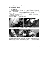
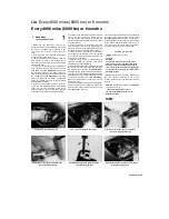
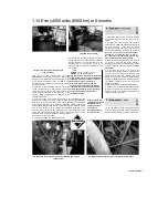
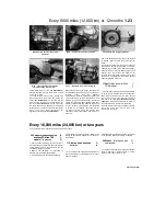
4.5a On TDM models, detach the No. 1
vacuum hose (arrowed) from the fuel
pump...
4.5b ... and remove the blanking plug
(arrowed) from the No. 2 hose
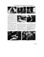
A
4.6 On TRX models, detach the No. 2
vacuum hose (arrowed) from the fuel
pump
Содержание XTZ750
Страница 174: ...UNREGISTERED VI ScanedbyStalker UNREGISTERED VI ...
Страница 207: ...Wiring diagrams 9 29 _____Scaned by Stalker 5 l 6o Cxj fi I JICM ...
Страница 208: ...UNREGISTERED VI 9 30 Wiring diagrams UNREGISTERED VERSION 01 ONREGISTEREDVI Scaned by Stalker ONREGISTERED VERSION 0 ...
Страница 209: ...I UNREGISTERED VI Wiring diagrams 9 31 ____ Scaned by Stalker UNREGISTERED VERSION OF PICTURE DESK ...
Страница 210: ...9 32 Wiring diagrams Scaned by Stalker ...
Страница 211: ...XTZ750 gauge Starter circuit Neutral Starter cut off relay switch rnotor ...

