2*18 Engine, clutch
and
transmission
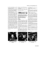
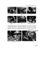
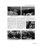
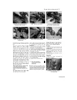
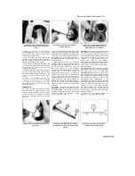
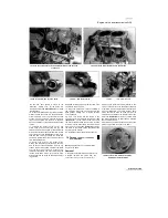
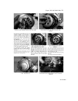
9.5 Release the ratchet and press the
plunger In
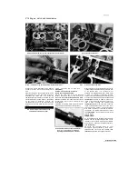
9.8a Install the tensioner using a new
gasket
...
9.8b ... and tighten the mounting bolts to the
specified torque
9.9 Install the springs and cap bolt
5
Release the ratchet mechanism from the
tensioner plunger and check that the plunger
moves freely in and out of the tensioner body
(see illustration).
6
If the tensioner or any of its components are
worn or damaged, or if the plunger is seized in
the body, the tensioner must be renewed -
individual components are not available.
Installation
7 Release the ratchet mechanism and press the
tensioner plunger all the way into the tensioner
body
(see illustration 9.5).
8
Fit a new gasket onto the tensioner body, then
install the tensioner in the engine and tighten
the bolts to the torque setting
specified at the beginning of the Chapter
(see
illustrations).
9
Install the springs and cap bolt, with its
washer, and tighten the bolt to the specified
torque setting
(see illustration).
10
Remove the alternator cover centre plug and
turn the crankshaft anti-clockwise through two full
turns using a socket on the rotor bolt
(see
illustrations 8.2a and b).
This will allow the
tensioner to set itself properly. Use a new O-ring
on the centre plug.
11
It is advisable to remove the valve cover
(see Section 7) and check that the cam chain is
tensioned and all the timing marks are in
alignment (see Section 8). If the chain is slack,
the tensioner plunger did not release when the
spring and cap bolt were installed. Remove the
tensioner again and re-check it. Again check the
timing marks (see Section 8), then install the
valve cover (see Section 7).
10 Cylinder head
-
fb
removal and installation
gs
Caution:
The engine must be completely cool
before beginning this procedure or the
cylinder head may become warped.
Note 1:
The cylinder head can be removed
with the engine in the frame. If the engine has
been removed, ignore the steps which don't
apply.
Note 2:
If no work is being carried out on the
valves, the cylinder head can be removed with
the camshafts in place. Holes in the camshafts
and in the right-hand camshaft holders allow
access to the cylinder head nuts. The camshaft
sprockets must be removed.
Removal
1
Remove the valve cover (see Section 7), the
camshaft sprockets (see Section 8), and if
required the camshafts (see Note 2 above). If the
camshafts are being left in place, remove the
blanking cap from the top of each right-hand
camshaft holder, then turn the camshafts using a
screwdriver or rod through the hole in the middle
of the camshaft until the access holes in the
shafts align with the cylinder head nuts
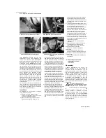
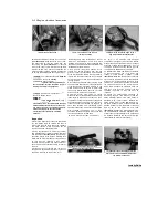
(see
illustration).
If the camshafts are left in place,
the nuts and washers cannot be removed after
they have been loosened as the camshafts will
be in the way.
2 Remove the exhaust system (see Chapter 4).
3 If not already done, remove the cam chain
front guide (see Section 24).
4 If required, release the clamp(s) securing the
vacuum hose(s) to the inlet manifold(s) and
detach the hose(s).
5 Unscrew the oil pipe banjo bolt from the
cylinder head and detach the pipe from the
cylinder head
(see illustration).
Discard the
banjo bolt sealing washers as new ones must be
used.
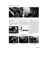
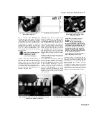
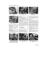
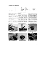
10.1 Remove the blanking caps (A) from
the holes in the holders. Turn the shafts
using the centre holes (B) until the access
holes in each camshaft align with the nuts
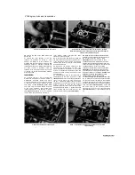
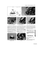
10.5 Unscrew the banjo bolt (arrowed) and
detach the oil pipe
10.6a On TDM models, remove the
cylinder head-to-bracket bolt (arrowed) on
each side
Staned by Stalker
Содержание XTZ750
Страница 174: ...UNREGISTERED VI ScanedbyStalker UNREGISTERED VI ...
Страница 207: ...Wiring diagrams 9 29 _____Scaned by Stalker 5 l 6o Cxj fi I JICM ...
Страница 208: ...UNREGISTERED VI 9 30 Wiring diagrams UNREGISTERED VERSION 01 ONREGISTEREDVI Scaned by Stalker ONREGISTERED VERSION 0 ...
Страница 209: ...I UNREGISTERED VI Wiring diagrams 9 31 ____ Scaned by Stalker UNREGISTERED VERSION OF PICTURE DESK ...
Страница 210: ...9 32 Wiring diagrams Scaned by Stalker ...
Страница 211: ...XTZ750 gauge Starter circuit Neutral Starter cut off relay switch rnotor ...

