2*38 Engine, clutch and transmission
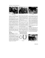
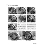
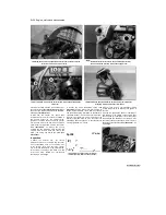
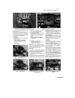
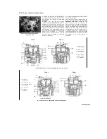
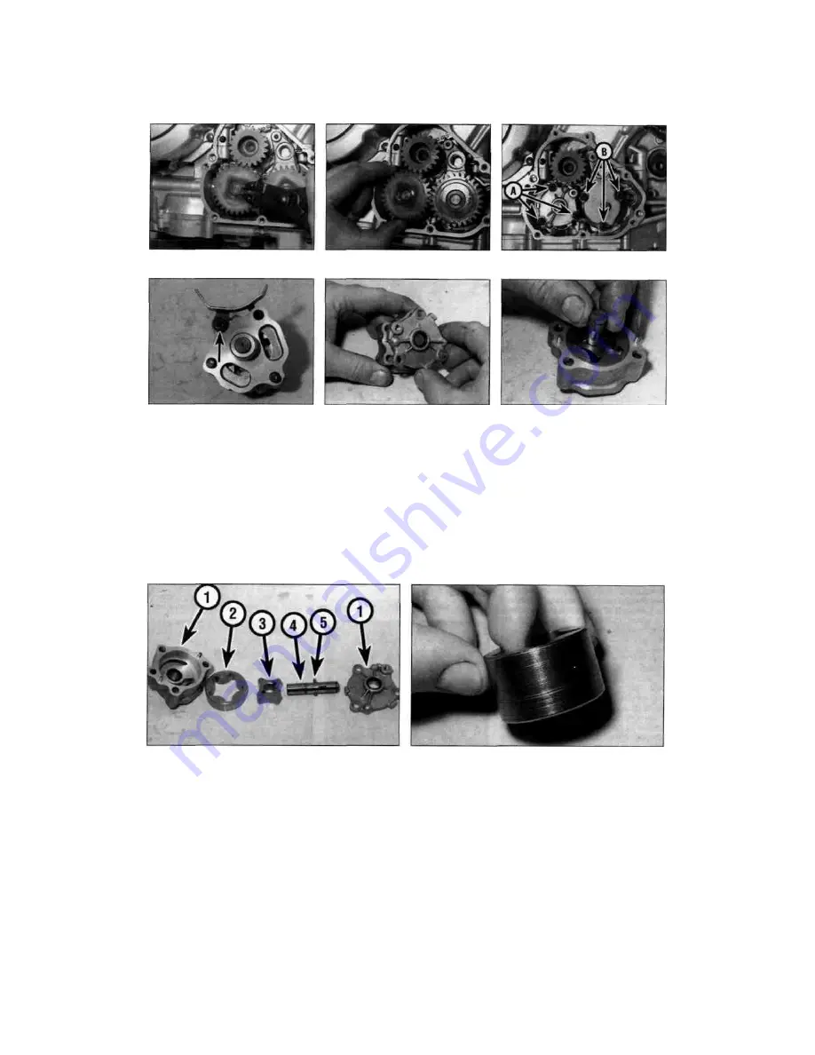
20.5a Remove the circlip.
20.5b ... and slide off the gear
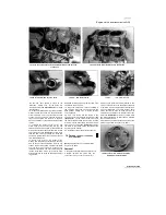
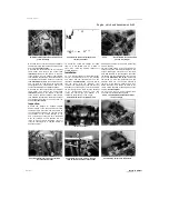
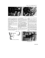
20.6 Feed pump screws (A), scavenge
pump screws (B)
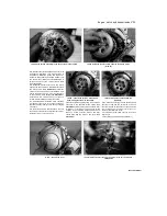
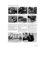
20.7a Remove the screw (arrowed)
.
Discard the gasket as a new one must be used.
Remove the dowels from either the cover or the
crankcase if they are loose. Also note the oil
passage collar located in the orifice in the
scavenge pump cover. Discard the O-ring as a
new one must be used, and remove the collar if
required
(see illustration 20.18).
5
Remove the circlip securing the oil pump
driven gear to the feed pump shaft and remove
the gear
(see illustrations).
Discard the circlip
as a new one should be used. Do the same to
free the driven gear from the scavenge pump.
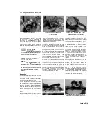
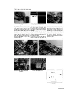
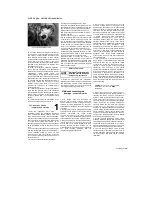
20.7b ... and separate the housing
6
Each pump is secured by three screws
(see
illustration).
Remove the screws and remove
the pump, noting how it fits. Discard the
gasket as a new one must be used. Note the
dowel locating the scavenge pump and
remove it if it is loose.
Inspection
7 If required, the pumps can be disassembled
for cleaning. Remove the single assembly screw
and separate the pump housing, on the feed
pump noting how the cam chain guide fits
(see
illustrations).
Remove the housing locating pins
if they are loose. Draw the inner rotor with the
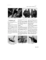
20.7c Draw out the shaft and remove the
rotors
driveshaft out of the pump housing, then remove
the outer rotor
(see illustration).
Note which way
round the rotors fit and how the driveshaft pin
locates in the slots in the inner rotor.
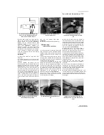
8 Clean all the components in solvent
(see
illustration).
9
Inspect the pump body and rotors for scoring
and wear
(see illustration).
If any damage,
scoring or uneven or excessive wear is evident,
renew the pump (individual components are not
available).
10 Fit the outer rotor into the pump body. Fit
the drive pin into the shaft, then slide the shaft
into the inner rotor, locating the drive pin ends
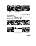
20.8 Oil pump components
1 Housing 2 Outer rotor 3 Inner rotor 4 Shaft 5 Drive pin
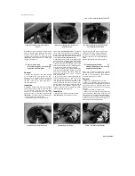
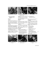
20.9 Look for scoring and wear, such as on this outer rotor
Scaned by Stalker
Содержание XTZ750
Страница 174: ...UNREGISTERED VI ScanedbyStalker UNREGISTERED VI ...
Страница 207: ...Wiring diagrams 9 29 _____Scaned by Stalker 5 l 6o Cxj fi I JICM ...
Страница 208: ...UNREGISTERED VI 9 30 Wiring diagrams UNREGISTERED VERSION 01 ONREGISTEREDVI Scaned by Stalker ONREGISTERED VERSION 0 ...
Страница 209: ...I UNREGISTERED VI Wiring diagrams 9 31 ____ Scaned by Stalker UNREGISTERED VERSION OF PICTURE DESK ...
Страница 210: ...9 32 Wiring diagrams Scaned by Stalker ...
Страница 211: ...XTZ750 gauge Starter circuit Neutral Starter cut off relay switch rnotor ...

