UNREGISTERED VI
6»16 Frame, suspension and final drive
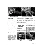
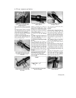
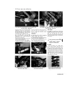
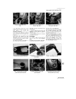
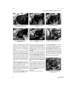
through the fork tube and engages the damper
rod head; a similar tool can be easily made in the
home workshop..
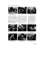
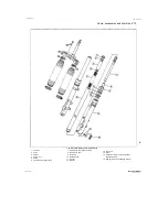
67 Invert the fork and withdraw the damper rod
from inside the fork tube
(see illustration 7.38).
If required, slide the rebound spring off the
damper rod.
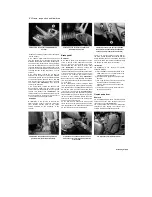
68 Carefully prise out the dust seal from the top
of the slider to gain access to the oil seal
retaining clip
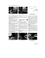
(see illustration 7.10).
Discard the
dust seal as a new one must be used.
69 Carefully remove the retaining clip, taking
care not to scratch the surface of the tube
(see
illustration 7.11).
70
To separate the tube from the slider it is
necessary to displace the top bush and oil seal.
The bottom bush should not pass through the top
bush, and this can be used to good effect. Push
the tube gently inwards until it stops against the
damper rod seat. Take care not to do this forcibly
or the seat may be damaged. Then pull the tube
sharply outwards until the bottom bush strikes the
top bush. Repeat this operation until the top bush
and seal are tapped out of the slider
(see
illustration 7.12).
71
With the tube removed, slide off the oil seal,
washer and top bush, noting which way up they
fit
(see illustration 7.13).
Discard the oil seal as
a new one must be used.
Caution: Do not
remove the bottom bush from the tube unless
it is to be renewed.
72 Tip the damper rod seat out of the slider,
noting which way up it fits.
Inspection
73
Clean all parts in solvent and blow them dry
with compressed air, if available. Check the fork
tube for score marks, scratches, flaking of the
chrome finish and excessive or abnormal wear.
Look for dents in the tube and renew the tube in
both forks if any are found. Check the fork seal
seat for nicks, gouges and scratches. If damage
is evident, leaks will occur. Also check the oil
seal washer for damage or distortion and renew it
if necessary.
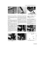
74 Check the fork tube for runout (bending)
using V-blocks and a dial gauge, or have it done
by a dealer
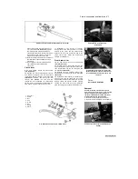
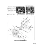
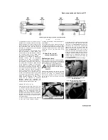
(see illustration 7.16).
Yamaha do
not specify a runout limit, but if the tube is bent it
should be renewed.
75 Check the spring for cracks and other
damage. Measure the spring free length and
compare the measurement to the specifications
at the beginning of the Chapter. If it is defective
or sagged below the service limit, renew the
springs in both forks. Never renew only one
spring. Also check the rebound spring.
76
Examine the working surfaces of the two
bushes; if worn or scuffed they must be renewed.
To remove the bottom bush from the fork tube,
prise it apart at the slit using a flat-bladed
screwdriver and slide it off
(see illustration
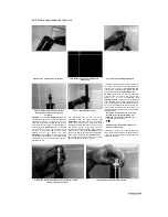
7.18).
Make sure the new one seats properly.
77 Check the damper rod for damage and
wear, and renew it if necessary.
Reassembly
78
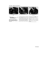
If removed, slide the rebound spring onto the
rod. Insert the damper rod into the fork tube and
slide it into place so that it projects fully from the
bottom of the tube, then fit the seat onto the
bottom of the damper rod
(see illustration 7.38
and 7.20b).
79
Oil the fork tube and bottom bush with the
specified fork oil and insert the assembly into the
slider. Fit a new copper sealing washer to the
damper rod bolt and apply a few drops of a
suitable
non-permanent
thread
locking
compound, then install the bolt into the bottom of
the slider
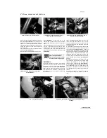
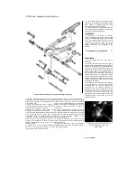
(see illustration 7.21).
Tighten the bolt
to the specified torque setting. If the damper rod
rotates inside the tube, use the tool described in
Step 66 to hold the damper rod.
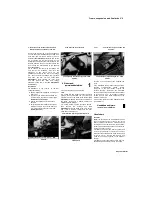
80 Push the fork tube fully into the slider, then
oil the top bush and slide it down over the tube
(see illustration 7.22a).
Press the bush squarely
into its recess in the slider as far as possible,
then install the oil seal washer
(see illustration
7.22b).
Either use the Yamaha service tool or a
suitable piece of tubing to tap the bush fully into
place; the tubing must be slightly larger in
diameter than the fork tube and slightly smaller in
diameter than the bush recess in the slider. Take
care not to scratch the fork tube during this
operation; it is best to make sure that the fork
tube is pushed fully into the slider so that any
accidental scratching is confined to the area
above the oil seal.
81
When the bush is seated fully and squarely
in its recess in the slider, (remove the washer to
check, wipe the recess clean, then reinstall the
washer), install the new oil seal. Smear the sealis
lips with lithium-base grease and slide it over the
tube so that its markings face upwards and drive
the seal into place as described above until the
retaining clip groove is visible above the seal
(see illustration 7.23).
Place the old oil seal on top
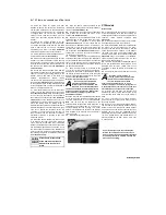
HINT
of the new one to protect It
when driving the seal into
place.
82
Once the seal is correctly seated, fit the
retaining clip, making sure it is correctly located
in its groove
(see illustration 7.24).
83
Lubricate the lips of the new dust seal then
slide it down the fork tube and press it into
position
(see illustration 7.25).
84
Slowly pour in the specified quantity of the
specified grade of fork oil and pump the fork at
least ten times to distribute it evenly
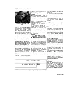
(see
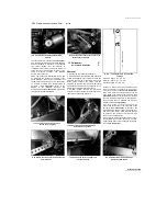
illustration 7.26a);
the oil level should also be
measured and adjustment made by adding or
subtracting oil. Fully compress the fork tube into
the slider and measure the fork oil level from the
top of the tube
(see illustration 7.26b).
Add or
subtract fork oil until it is at the level specified at
the beginning of the Chapter.
85 Clamp the slider in a soft-jawed vice using
the brake caliper mounting lugs, taking care not to
overtighten and damage them. Pull the fork tube
out of the slider as far as possible then install the
spring, the spring seat, with its shouldered side
fitting down into the top of the spring, and the
spacer.
86 Apply a smear of grease to the new top bolt
O-ring and thread the bolt into the top of the fork
tube.
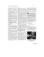
Warning: It will be necessary to
compress the spring by pressing it
down using the top bolt to engage the
threads of the top bolt with the fork
tube. This is a potentially dangerous operation
and should be performed with care, using an
assistant if necessary. Wipe off any excess oil
before starting to prevent the possibility of
slipping.
Keep the fork tube fully extended whilst
pressing on the spring. Screw the top bolt carefully
into the fork tube making sure it is not cross-
threaded.
Note:
The top bolt can be tightened to
the specified torque setting at this stage if the tube
is held between the padded jaws of a vice, but do
not risk distorting the tube by doing so (see
Tool
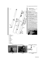
Tip).
A better method is to tighten the top bolt
when the fork has been installed in the bike and is
securely held in the bottom yoke.
87
Install the forks (see Section 6).
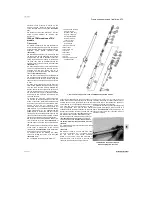
8 Steering stem -
removal and installation
Removal
1 Remove the front forks (see Section 6).
2 On TDM models, displace the handlebars from
the top yoke (see Section 5), then disconnect the
horn wiring connectors and unscrew the bolts
securing the front brake hose/horn bracket to the
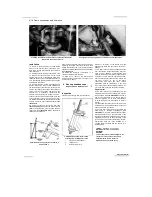
bottom yoke
(see illustration).
On 1996-on
models, unscrew the bolts securing the choke
knob and the cable guide to the top yoke.
Staned by Stalker
UNREGISTERED VERSION OF PICTURE-DESK
A
|
8.2 Disconnect the horn wiring connectors
(A), then unscrew the bolts (B) and
displace the brake hose union/horn
assembly
Содержание XTZ750
Страница 174: ...UNREGISTERED VI ScanedbyStalker UNREGISTERED VI ...
Страница 207: ...Wiring diagrams 9 29 _____Scaned by Stalker 5 l 6o Cxj fi I JICM ...
Страница 208: ...UNREGISTERED VI 9 30 Wiring diagrams UNREGISTERED VERSION 01 ONREGISTEREDVI Scaned by Stalker ONREGISTERED VERSION 0 ...
Страница 209: ...I UNREGISTERED VI Wiring diagrams 9 31 ____ Scaned by Stalker UNREGISTERED VERSION OF PICTURE DESK ...
Страница 210: ...9 32 Wiring diagrams Scaned by Stalker ...
Страница 211: ...XTZ750 gauge Starter circuit Neutral Starter cut off relay switch rnotor ...

