UNREGISTERED VERSION OF PICTURE-DESK
7*16 Brakes, wheels and tyres
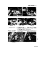
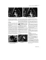
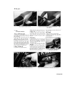
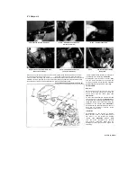
Now tighten the axle clamp bolt on the bottom of
the right-hand fork to 'he specified torque setting
(see illustration 11.4).
14
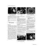
On XTZ models, fit the washer and axle nut,
then counter-hold the head of the axle and
tighten the nut to the torque setting specified at
the beginning of the Chapter. Fit a new split
through the end of the axle
(see illustration
11.5).
Install the disc covers.
15
Install the brake calipers, making sure the
pads sit squarely on either side of the discs (see
Section 3). Tighten the caliper mounting bolts to
the specified torque setting.
16 Fit the speedometer cable into the drive
housing and tighten the knurled ring securely
(see illustrations 11.3 and 11.5).
On 1991 TDM
models
if
the
speedometer
wiring
was
disconnected, remake the 3-pin connector and
secure the wiring to the brake hose and the guide
provided on the brake caliper lower mounting
bolt; use the proper clips to the secure the wire to
the brake hose and don't fasten them too tight
otherwise the hose will be distorted.
17
Apply the front brake a few times to bring the
pads back into contact with the discs. Move the
motorcycle off the stand, apply the front brake
and pump the front forks a few times to settle all
components in position.
18 Check for correct operation of the front brake
before riding the motorcycle.
12 Rear wheel
-
f^
removal and installation
|§
Removal
1
Position the motorcycle on an auxiliary stand
so that the wheel is off the ground. On XTZ
models, unscrew the bolts securing the rear
brake caliper shield and remove the cover
(see
illustration 3.1).
2
Remove the brake caliper mounting bolts and
slide the caliper off the disc (see Section 3).
Support the caliper with a piece of wire or a
bungee cord so that no strain is placed on the
hydraulic hose. There is no need to disconnect
the hose from the caliper.
Note:
Do not operate
the brake pedal with the calipers removed.
On
TDM models, slacken the caliper bracket bolt on
the swingarm
(see illustration).
3
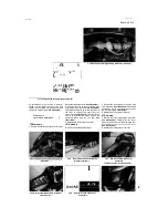
Where fitted, remove the split pin from the axle
nut on the end of the axle
(see illustration).
Unscrew the axle nut and remove the washer,
and on TRX models the adjuster position marker
(see illustration).
4
Support the wheel then withdraw the axle and
lower the wheel to the ground
(see illustration).
On TRX models, retrieve the adjustment position
marker. Note how the caliper bracket locates
between the wheel and the swingarm.
5
Disengage the chain from the sprocket and
remove the wheel from the swingarm
(see
illustration 12.10).
Caution: Do not lay the wheel down and allow
it to rest on the disc or the sprocket
-
they
could become warped. Set the wheel on wood
blocks
so
the disc or the sprocket doesn't
support the weight of the wheel. Do not
operate the brake pedal with the wheel
removed.
6
Check the axle for straightness by rolling it on
a flat surface such as a piece of plate glass (first
wipe off all old grease and remove any corrosion
using fine emery cloth). If the axle is bent, renew
it.
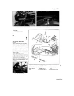
7 Remove the collar from each side of the
wheel,
noting
which
fits
where
(see
illustrations).
Check the condition of the grease
seals and wheel bearings (see Section 13).
Installation
8 Apply a thin coat of lithium-based grease to
the lips of each grease seal, and also to the
collars and the axle. On TRX models, slide the
right-hand adjustment position marker onto the
axle, making sure it is the correct way round.
9 Install the short collar into the left-hand side of
the wheel and the long shouldered collar into the
right-hand side
(see illustrations 12.7b and a).
Manoeuvre the wheel so that it is in between the
ends of the swingarm. Align
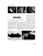
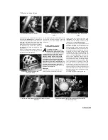
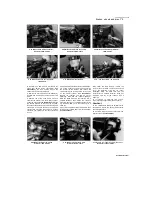
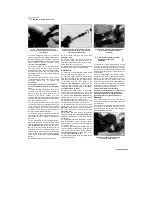
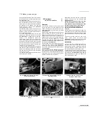
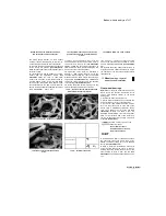
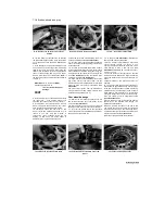
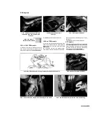
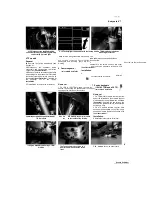
12.2 On TDM models, slacken the caliper
bracket bolt (arrowed)
12.3a Rear axle nut and split pin -1991 to
1995 TDM models
12.3b Rear axle nut (A) and position
marker (B) - TRX models
12.4 Withdraw the axle and remove the
wheel
12.7a Remove the collar from each
side
...
12.7b ... noting which way round they fit
Staged by Stalker
ONREGISTERED VERSION OF PICTORE-DESK
Содержание XTZ750
Страница 174: ...UNREGISTERED VI ScanedbyStalker UNREGISTERED VI ...
Страница 207: ...Wiring diagrams 9 29 _____Scaned by Stalker 5 l 6o Cxj fi I JICM ...
Страница 208: ...UNREGISTERED VI 9 30 Wiring diagrams UNREGISTERED VERSION 01 ONREGISTEREDVI Scaned by Stalker ONREGISTERED VERSION 0 ...
Страница 209: ...I UNREGISTERED VI Wiring diagrams 9 31 ____ Scaned by Stalker UNREGISTERED VERSION OF PICTURE DESK ...
Страница 210: ...9 32 Wiring diagrams Scaned by Stalker ...
Страница 211: ...XTZ750 gauge Starter circuit Neutral Starter cut off relay switch rnotor ...

