UNREGISTERED VERSION OF PICTURE-DESK |
UNREGISTERED VERSION OF PICTURED
6*18 Frame, suspension and final drive
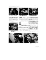
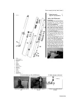
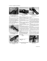
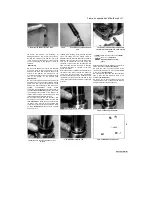
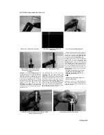
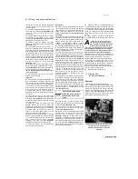
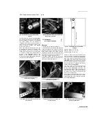
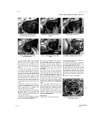
8.12 Align the adjuster nut and locknut so that the lockwasher
tabs fit into the notches in both
8.13 Tighten the steering stem nut or bolt to the specified torque
Installation
10 Smear a liberal quantity of lithium-based
grease on the bearing races in the frame. Also
work some grease well into both the upper and
lower bearings.
11
Carefully lift the steering stem/bottom yoke
up through the steering head. Fit the upper
bearing into the top of the steering head, then
install the bearing cover. Thread the adjuster nut
onto the steering stem and adjust the bearings
as described in Chapter 1.
12
On TDM and TRX models, install the washer
and the locknut. On 1991 to 1995 TDM models
the tapered side of the locknut must face down.
Tighten the locknut finger-tight, then tighten it
further until its notches align with those in the
adjuster nut. If necessary, counter-hold the
adjuster nut and tighten the locknut using a C-
spanner or drift until the notches align, but make
sure the adjuster nut does not turn as well. Install
the tabbed lockwasher so that the tabs fit into the
notches in both the locknut and adjuster nut
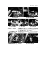
(see
illustration).
13
Fit the top yoke onto the steering stem
(see
illustration 8.5b),
then install the washer (where
fitted) and steering stem nut or bolt and tighten it
finger-tight
(see illustration 8.5a).
Temporarily
install one of the forks to
align the top and bottom yokes, and secure it by
tightening the bottom yoke clamp bolt only. Now
tighten the steering stem nut or bolt to the torque
settings specified at
the
beginning of the Chapter
(see illustration).
14
Install the remaining components in a
reverse of the removal procedure.
15 Carry out a check of the steering head
bearing freeplay as described in Chapter 1, and
if necessary re-adjust.
9 Steering head bearings
- ^
inspection and replacement *£
Inspection
1
Remove the steering stem (see Section 8).
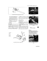
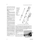
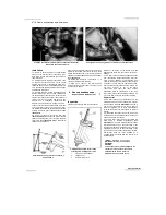
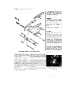
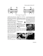
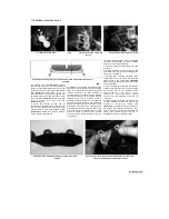
9.6 Drawbolt arrangement for fitting
steering stem bearing outer races
1
Long bolt or threaded bar
2
Thick washer
3
Guide for lower race
2
Remove all traces of old grease from the
bearings and races and check them for wear or
damage.
3 The outer races should be polished and free
from indentations. Inspect the bearing rollers for
signs of wear, damage or discoloration, and
examine the bearing roller retainer cage for signs
of cracks or splits. Spin the bearings by hand.
They should spin freely and smoothly. If there are
any signs of wear on any of the above
components both upper and lower bearing
assemblies must be renewed as a set. Only
remove the races if they need to be renewed - do
not re-use them once they have been removed.
Replacement
4 The outer races are an interference fit in the
steering head and can be tapped from position
with a suitable drift
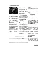
(see illustration).
Tap firmly
and evenly around each race to ensure that it is
driven out squarely. It may prove advantageous
to curve the end of the drift slightly to improve
access.
5 Alternatively, the races can be removed using
a slide-hammer type bearing extractor; these can
often be hired from tool shops.
6 The new outer races can be pressed into the
head using a drawbolt arrangement
(see
illustration),
or by using a large diameter tubular
drift which bears only on the outer edge of the
race. Ensure that the drawbolt washer or drift (as
applicable) bears only on the outer edge of the
race and does not contact the working surface.
Alternatively, have the races installed by a
Yamaha dealer equipped with the bearing race
installing tools.
|tflflfgg|
Installation of new bearing
UWilifii
outer races is made much
HiNT
easier
if the races are left overnight in the
freezer. This causes them to contract
slightly making them a looser fit.
Alternatively, use a freeze spray.
UNREGISTERED VERSION 0
Scaned by Stalker
UNREGISTERED VERSION OF PICTURE-DI
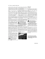
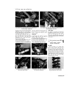
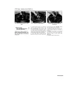
9.4 Drive the bearing outer races out with a
drift as shown
Содержание XTZ750
Страница 174: ...UNREGISTERED VI ScanedbyStalker UNREGISTERED VI ...
Страница 207: ...Wiring diagrams 9 29 _____Scaned by Stalker 5 l 6o Cxj fi I JICM ...
Страница 208: ...UNREGISTERED VI 9 30 Wiring diagrams UNREGISTERED VERSION 01 ONREGISTEREDVI Scaned by Stalker ONREGISTERED VERSION 0 ...
Страница 209: ...I UNREGISTERED VI Wiring diagrams 9 31 ____ Scaned by Stalker UNREGISTERED VERSION OF PICTURE DESK ...
Страница 210: ...9 32 Wiring diagrams Scaned by Stalker ...
Страница 211: ...XTZ750 gauge Starter circuit Neutral Starter cut off relay switch rnotor ...

