Frame, suspension and final drive 6*5
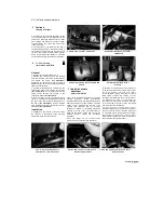
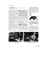
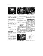
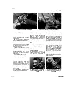
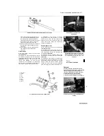
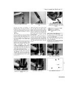
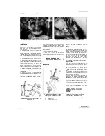
3.14a Slacken the locknuts (arrowed) and
thread the rod out of the lever and arm
3.14b Unscrew the pivot bolt.
3.14c
. and remove the lever, noting the
washers
lever and the arm (the rod is reverse-threaded on
one end and so will simultaneously unscrew from
both lever and arm when turned in the one
direction)
(see illustration).
Note the how far the
rod is threaded into the lever and arm as this
determines the height of the lever relative to the
footrest. Unscrew the pivot bolt and remove the
lever, noting the arrangement of the washers
(see illustrations).
15
To remove the lever with the linkage rod
and arm as an assembly, first note the
alignment
of
the
punch
mark
on
the
gearchange shaft with the slit in the linkage
arm, then unscrew the linkage arm pinchbolt
and slide the arm off the shaft
(see
illustrations).
Now unscrew the lever pivot
bolt and remove the lever and linkage
assembly, noting how it fits
(see illustrations
3.14b and c).
Installation
16
Installation is the reverse of removal,
noting the following:
a) Apply molybdenum disulphide oil to the gear
lever pivot
b) Align the punch mark on the shaft with the
slit in the clamp as noted on removal
(see
illustrations 3.1 Sa and bj.
c) Tighten the gearchange lever pivot bolt
securely.
d) Adjust the gear lever height
as
required by
screwing the rod in or out of the lever and
arm. Tighten the locknuts securely
(see
illustration 3.14a).
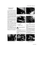
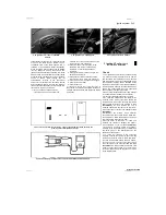
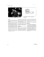
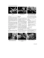
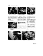
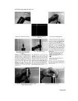
3.15a Linkage arm/shaft alignment
-
TDM
models
4 Sidestand -
removal and installation
1
Support the bike using an auxiliary
stand.
2 On TDM and XTZ models, unhook the stand
springs, then counter-hold the pivot bolt and
unscrew the nut on the inside of the bracket
(see
illustration).
Withdraw the pivot bolt and remove
the stand, noting how it locates against the
sidestand switch plunger.
3 On TRX models, unhook the stand springs,
then
unscrew
the
retaining
bolt
(see
illustration).
Slide the stand off its pivot, noting
how it fits. If required, counter-hold the pivot
piece and unscrew the nut
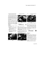
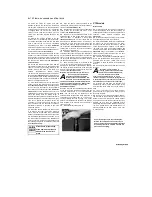
4.3 Sidestand retaining bolt (arrowed) ■
TRX models
3.15b Linkage arm/shaft alignment
-
TRX
models
securing it in the bracket, then withdraw the
pivot.
4 On installation apply grease to the pivot and a
suitable
non-permanent
thread
locking
compound to the bolt threads. Tighten the
nut/bolt securely. Reconnect the sidestand
spring and check that it holds the stand securely
up when not in use - an accident is almost
certain to occur if the stand extends while the
machine is in motion.
5 Check the operation of the sidestand switch
(see Chapter 1).
Handlebars and levers
-
removal and installation
Handlebars
Removal
Note:
The handlebars can be displaced from the
top yoke without having to remove any of the
lever or switch assemblies. On TRX models, the
handlebars can be removed from the handlebar
holders which clamp around the top of the forks,
leaving the holders in place.
1
Displace the front brake master cylinder and
reservoir (see Chapter 7). There is no need to
disconnect the hydraulic hose. Keep the reservoir
upright to prevent possible fluid leakage and
make sure no strain is placed on the hydraulic
hose(s).
2 Displace the throttle cable housing from the
handlebars (see Chapter 4). There is no need
Staged by Stalker
4.2 Sidestand pivot bolt (arrowed) - TDM
models
1
I
Содержание XTZ750
Страница 174: ...UNREGISTERED VI ScanedbyStalker UNREGISTERED VI ...
Страница 207: ...Wiring diagrams 9 29 _____Scaned by Stalker 5 l 6o Cxj fi I JICM ...
Страница 208: ...UNREGISTERED VI 9 30 Wiring diagrams UNREGISTERED VERSION 01 ONREGISTEREDVI Scaned by Stalker ONREGISTERED VERSION 0 ...
Страница 209: ...I UNREGISTERED VI Wiring diagrams 9 31 ____ Scaned by Stalker UNREGISTERED VERSION OF PICTURE DESK ...
Страница 210: ...9 32 Wiring diagrams Scaned by Stalker ...
Страница 211: ...XTZ750 gauge Starter circuit Neutral Starter cut off relay switch rnotor ...

