9*20 Electrical system
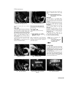
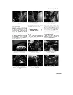
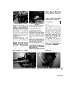
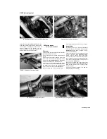
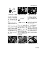
27.7 Pull back the covers to access the terminal nuts
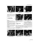
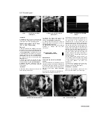
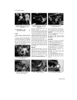
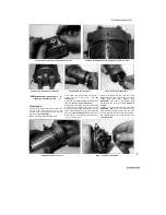
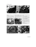
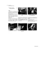
28.4a Unscrew the bolts (arrowed)
.
detach the leads
(see illustration).
Remove the
relay with its rubber sleeve from its mounting lug
on the frame. 8 Installation is the reverse of
removal. Make sure the terminal nuts are
securely tightened. Connect the negative (-ve)
lead last when reconnecting the battery.
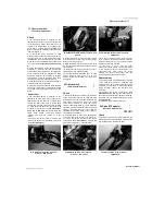
28.4b ... and remove the starter motor
28 Starter motor
-
removal and installation
Removal
1 Remove the seat (see Chapter 8). Disconnect
the battery negative (-ve) lead.
2 The starter motor is mounted underneath the
engine.
3 Peel back the rubber terminal cover and
remove the nut securing the starter lead to the
starter relay
(see illustration 27.2).
Detach the
lead and feed it through to the starter motor.
4 Unscrew the two bolts securing the starter
motor to the crankcase
(see illustration).
Slide
the starter motor out from the crankcase and
remove it from the machine
(see illustration).
5
Remove the O-ring on the end of the starter
motor and discard it as a new one must be used.
Installation
6
Install a new O-ring on the end of the starter
motor and ensure it is seated in its groove
(see
illustration).
Apply a smear of engine oil to the
O-ring to aid installation.
7 Manoeuvre the motor into position and slide it
into the crankcase
(see illustration 28.4b).
Ensure that the starter motor teeth mesh
correctly with those of the starter idle/reduction
gear. Install the mounting bolts and tighten them
to the torque setting specified at the beginning of
the Chapter
(see illustration).
8
Connect the starter lead to the starter relay
and secure it with the nut
(see illustration 27.2).
Make sure the rubber cover is correctly seated
over the terminal.
9 Connect the battery negative (-ve) lead and
install the seat (see Chapter 8).
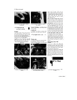
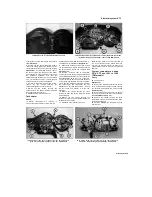
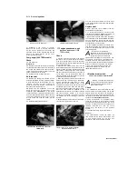
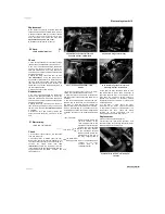
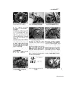
28.6 Fit a new O-ring into the groove
28.7 Install the bolts and tighten them to the specified torque
Scaned by Stalker
I
Содержание XTZ750
Страница 174: ...UNREGISTERED VI ScanedbyStalker UNREGISTERED VI ...
Страница 207: ...Wiring diagrams 9 29 _____Scaned by Stalker 5 l 6o Cxj fi I JICM ...
Страница 208: ...UNREGISTERED VI 9 30 Wiring diagrams UNREGISTERED VERSION 01 ONREGISTEREDVI Scaned by Stalker ONREGISTERED VERSION 0 ...
Страница 209: ...I UNREGISTERED VI Wiring diagrams 9 31 ____ Scaned by Stalker UNREGISTERED VERSION OF PICTURE DESK ...
Страница 210: ...9 32 Wiring diagrams Scaned by Stalker ...
Страница 211: ...XTZ750 gauge Starter circuit Neutral Starter cut off relay switch rnotor ...

